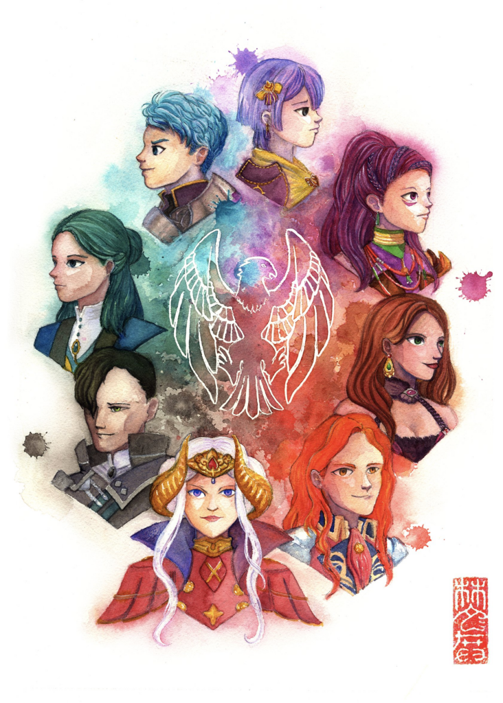
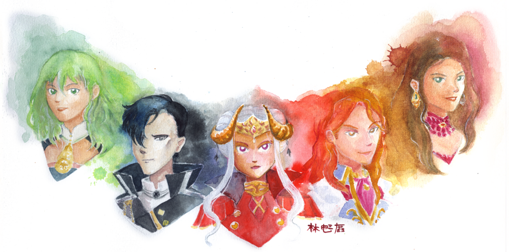
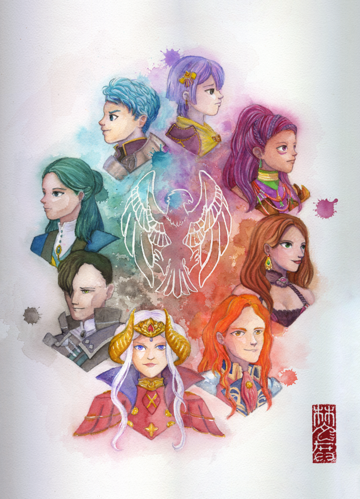
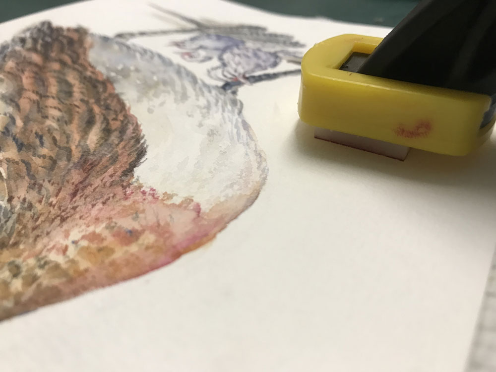
A Fire Emblem: Three Houses fan piece that took me over a year to take from concept to final painting.
I’m documenting this one here now because all the WIPs are in a Twitter thread and actually a blog post is probably a better medium for chronicling things and adding some thoughts.
I’ll start with thoughts on the final piece. I’ll admit, I’m not fully happy with how it came together. The colours are nice, but looking at it three years later, many of the faces are a bit weak. I think I was torn between how much detail to put into various parts of the image when working with watercolours, which can be temperamental – and I was trying to deliberately incorporate unpredictable elements like paint splatters to boot. I was probably too afraid of messing things up further with the faces to work them much more, including adjusting skintones. Some of this fear is justified – watercolours are not a medium that afford a lot of flexibility for adjustments or fixes.
Still, I think it’s fair to say the final piece suffers for my fearful approach.
I’m going to take you through all the test pieces that went into this piece and I think you’ll understand my disappointment after you see them – when there’s great elements in a test piece, their absences in the final artwork feel like a letdown.
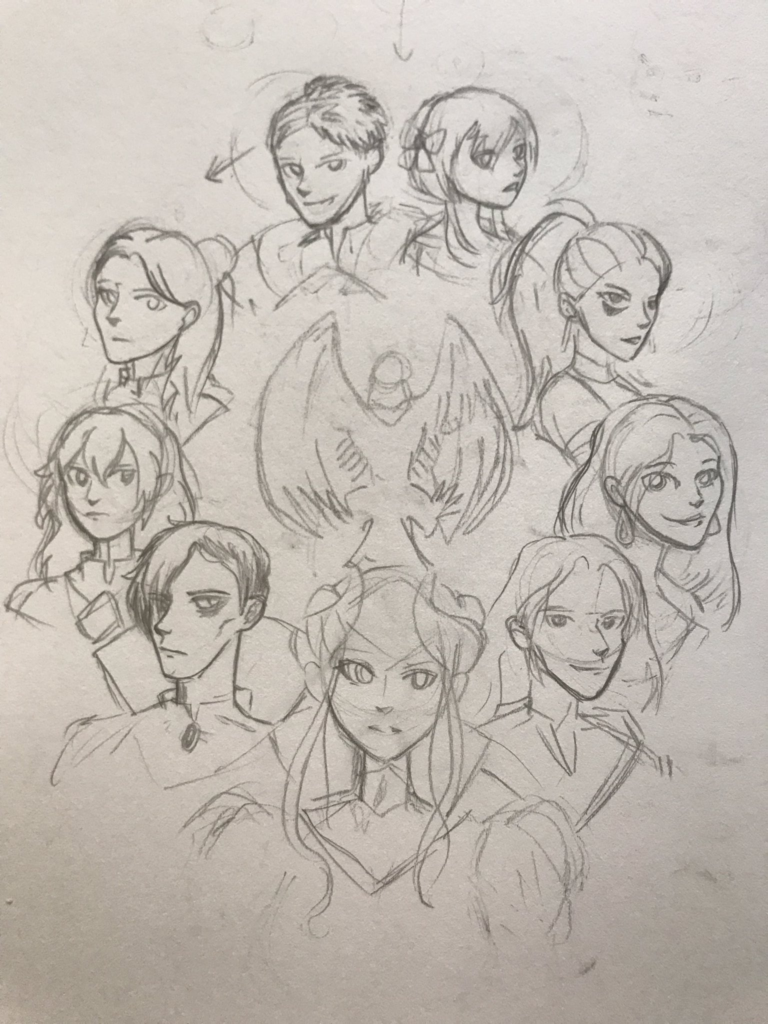
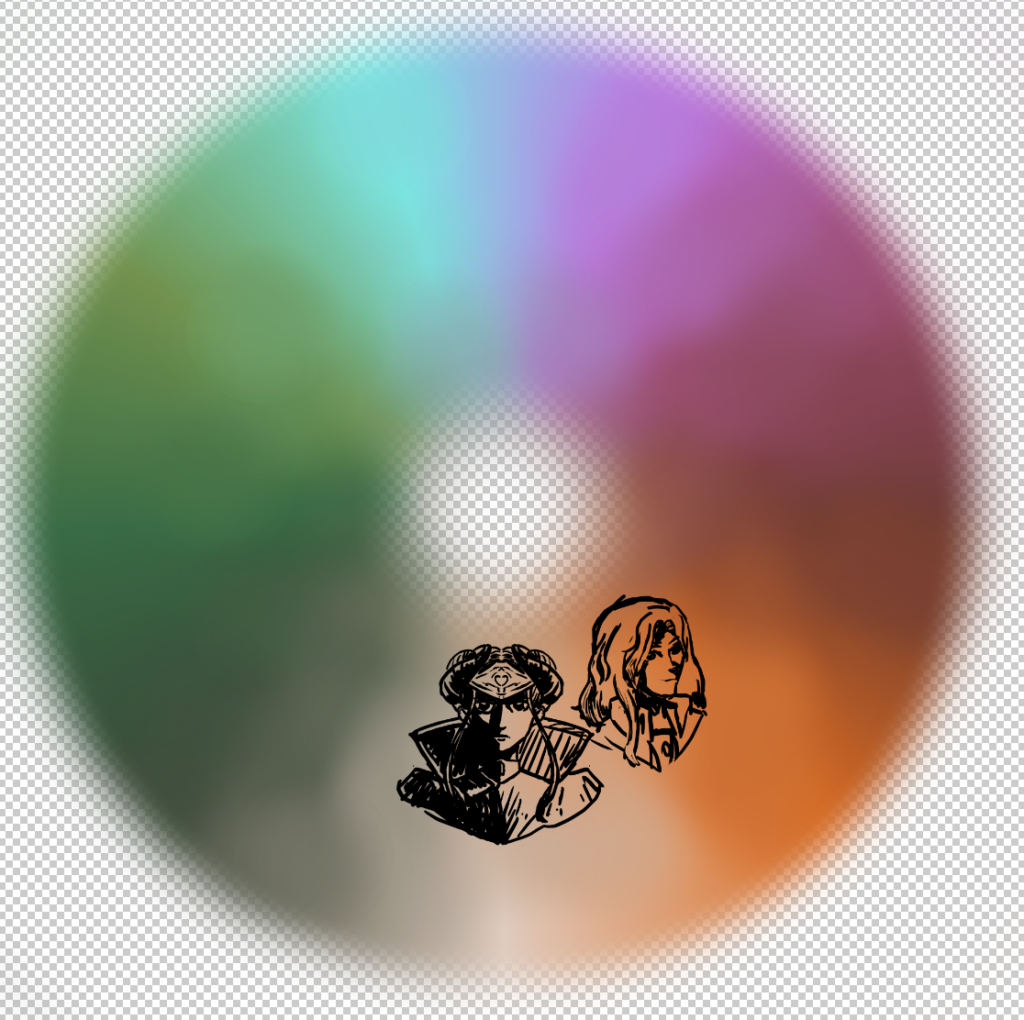
We’ll start with the very first scribble, which apparently was the product of insomnia. I think it was pen scribbled straight over a watercolour gradient.
After that, the idea for the full painting quickly formed – a circle to span the whole rainbow.
I was torn on whether to include Byleth or not in this – partly because I was unsure whether I’d try my hand at the other Houses as well. In the end, they didn’t make the cut.
After this, I did a ton of experiments for the colour bleeds.
I LOVE how this one was coming together. Unfortunately, I didn’t have enough space on the test paper to continue it. I think I spent the entirety of the rest of this undertaking trying to chase what I’d done in this piece. Argh!
Some style experiments. The paint splatters came out great in this one and the one below.
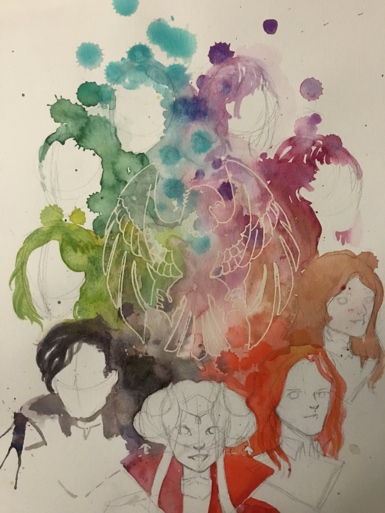
I think what I didn’t appreciate in my test pieces was how little space there’d be for splatters to not collide in the middle. I then tried to lean into it, placing the eagle logo in the centre where all the colours converged.
There was a lot of time between the test pieces and before I was finally ready to undertake the final piece. I think in the intervening time, I considered doing the entire painting digitally, and experimented with how that would look.
But eventually, I got back on track to do things in watercolour. That didn’t mean throwing out the digital tools! Instead, the composition was drafted digitally for tracing. Of course, it went through a couple iterations too.
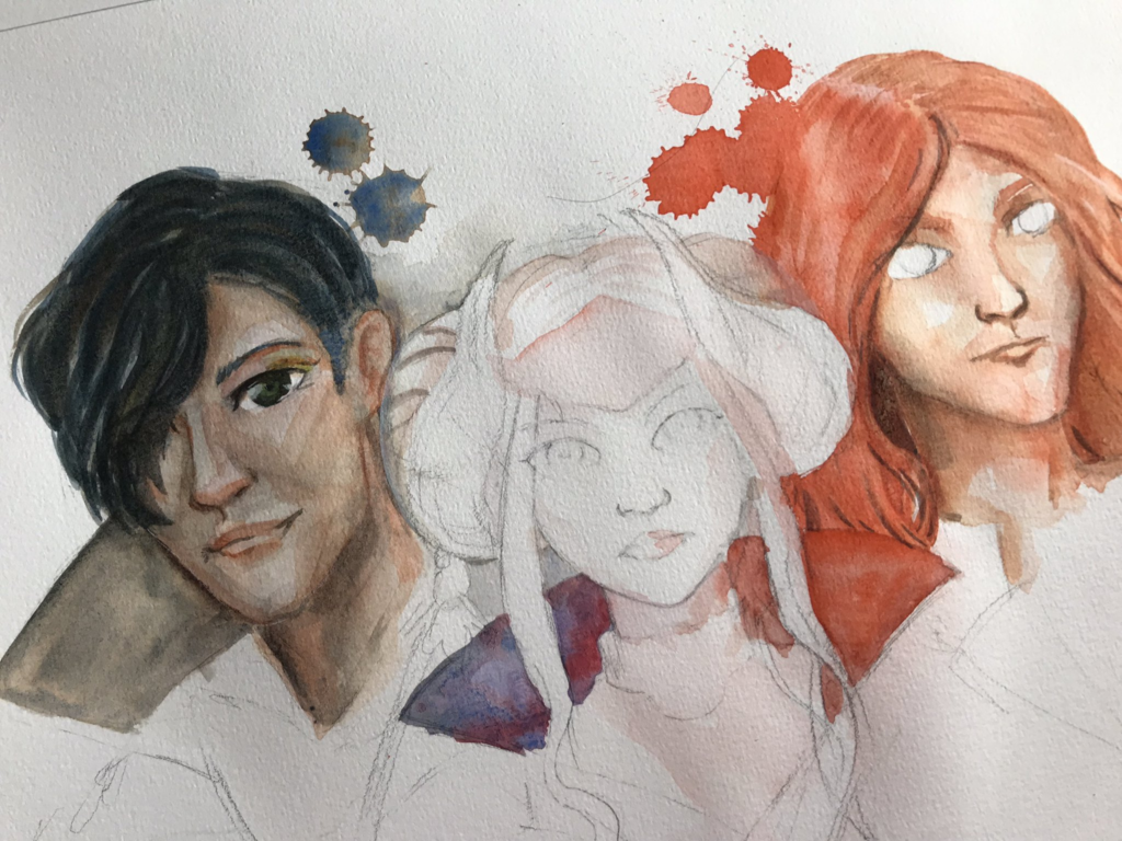
I think this tracing has made the sketch feel quite rigid as a result. Byleth was officially excommunicated.
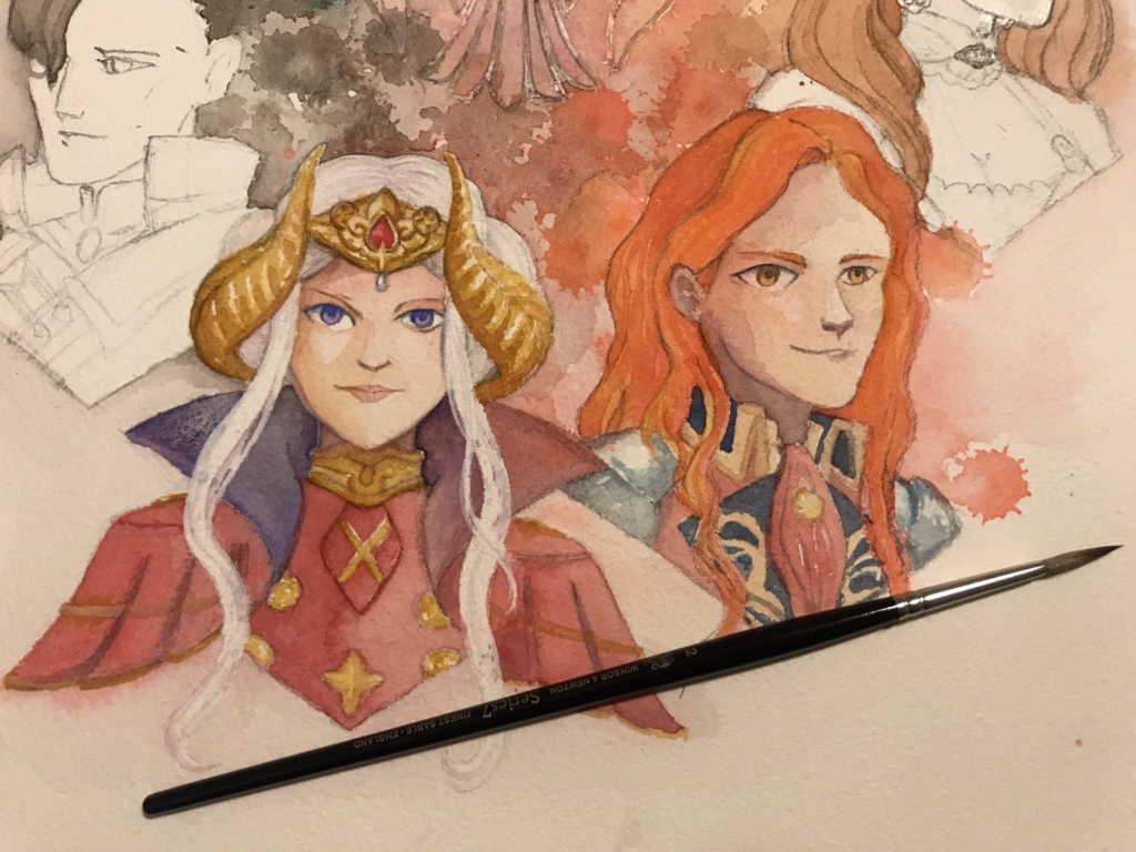
Here was how things were looking after the paint splatters were done. I definitely went into that scared.
Looking at this progress photo, I think I definitely oversaturated the scan. Maybe things could be helped somewhat with a colour retweak… ok, let’s look at these files.
Hang on a moment… what the heck? Looking at the files in my art folder… I already did a re-scan! It’s dated February 2022, about seven months after I originally posted the painting online. But I never posted the rescan? Or at least, not in the Twitter thread. Another reason why using Twitter as a digital archive is a bad idea…
Anyhow, here it is. I think there’s some definite improvements in the colours, and it looks like I adjusted some of the skintones. I wasn’t able to fix Dorothea’s dark blotchiness, but at least Petra doesn’t look so pale in comparison. I think one of the issues I had with the original painting was how dark the paper scanned, so when trying to eliminate the paper textures and shadows I ended up really pulling the colours in weird directions.
So I’ll present this version without trying to wash out the background to white. Still not perfect, but an improvement, I think. Maybe I should go in for a third try, sometime…
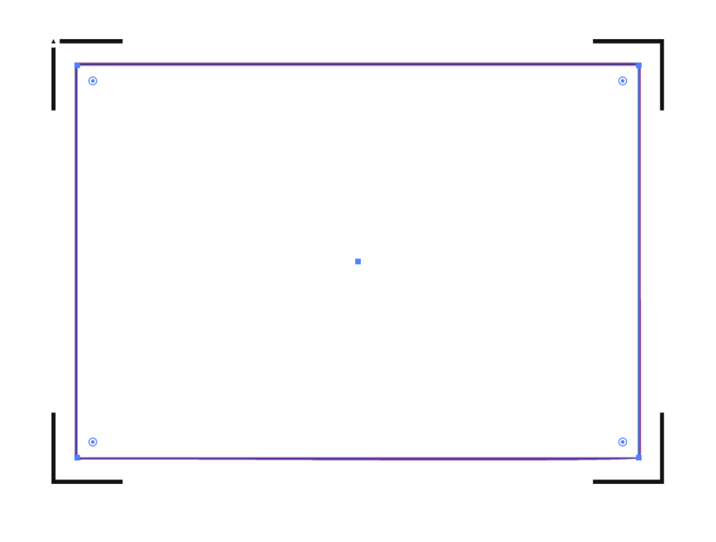
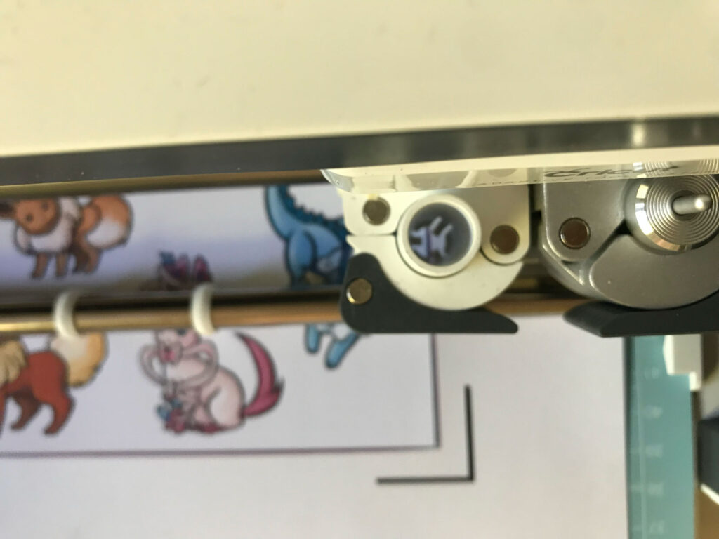
I’ve frequently felt constrained by the registration marks that the Cricut uses.
Understandably, they need to be bold and have a quiet region around them so that the cutter can determine where to line up its cuts.
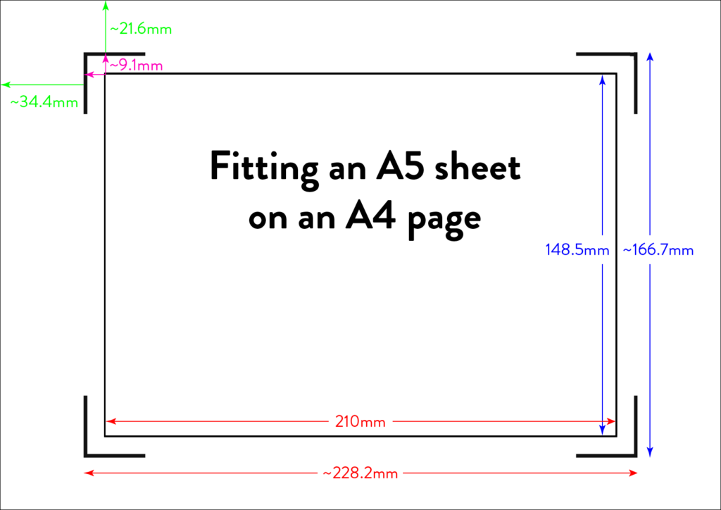
Cricut also currently only provides 4 preset page sizes to print on, and again seems to assume rather generous print margins.
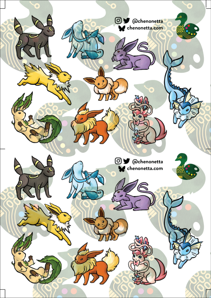
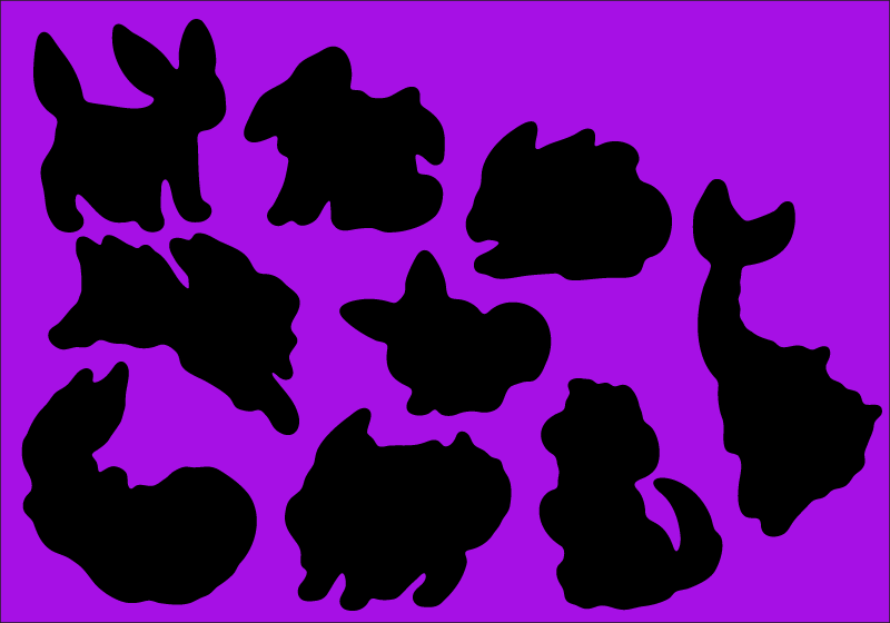
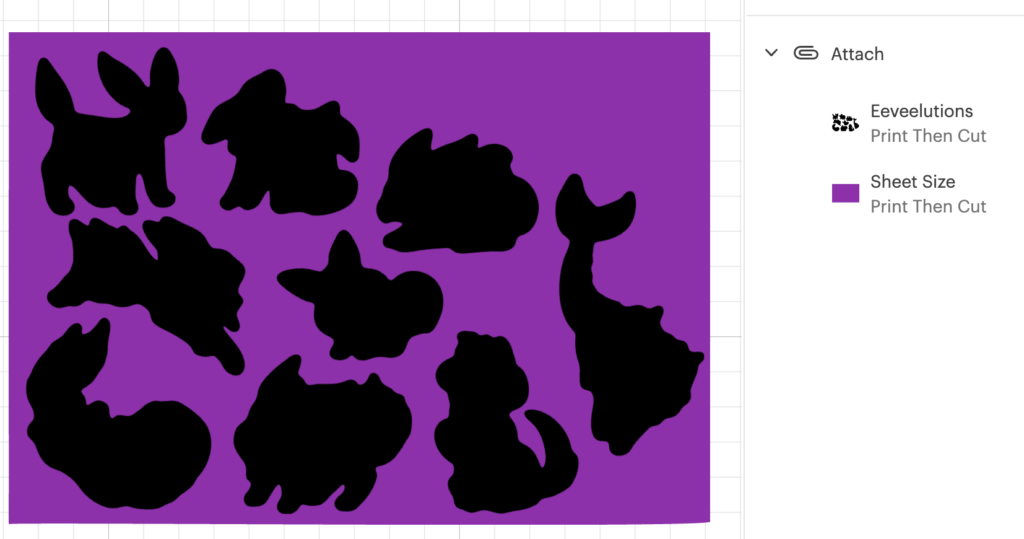
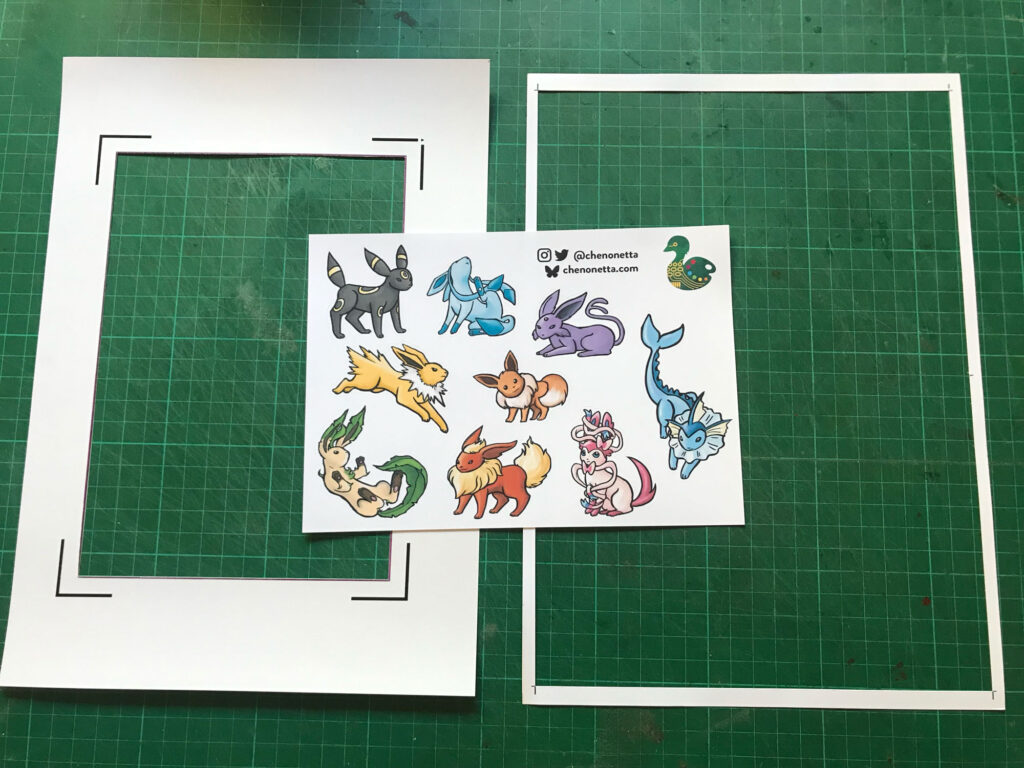
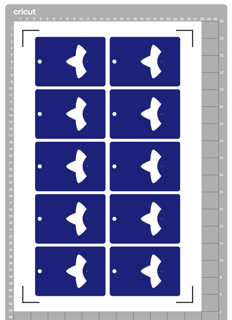
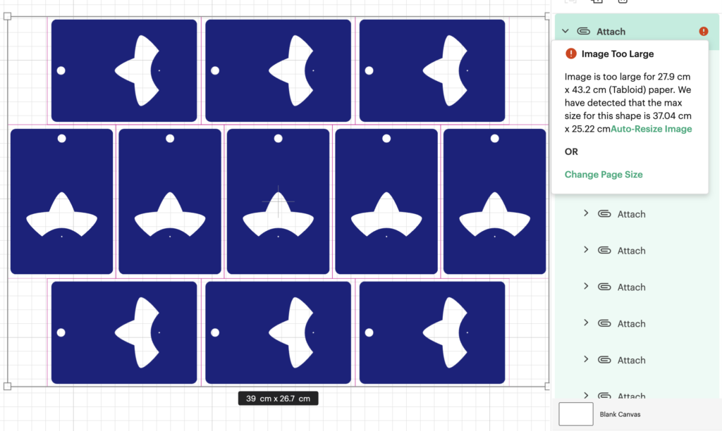
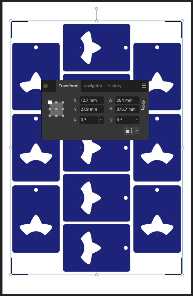
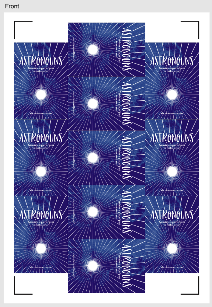
All these things added up mean that sometimes it’s not possible to place as many pieces on a page as you want. In the example above, I had to use a Tabloid paper size to convince Cricut to let me place the ten objects.
I reckon I should be able to fit even more of them in, and I should be able to do it on an A3 page. But Cricut says this layout is too large, despite the design itself being comfortably smaller than an A3 sheet.
(I’d actually love to fit even more than 11 onto an SRA3 page but making that layout work has so far eluded me, so let’s start with this hack first before trying anything more extreme.)
I discovered this hack by accident. I had taken my sheets to be printed at a print shop and they messed up the scaling. My pages came out about 3% smaller, but my Cricut didn’t complain. It happily executed the cutlines 3% smaller too. Evidently, there’s a generous margin of error for scaling.
So let’s use that to our advantage.
Step 1: Downsize the design in Cricut Design Space
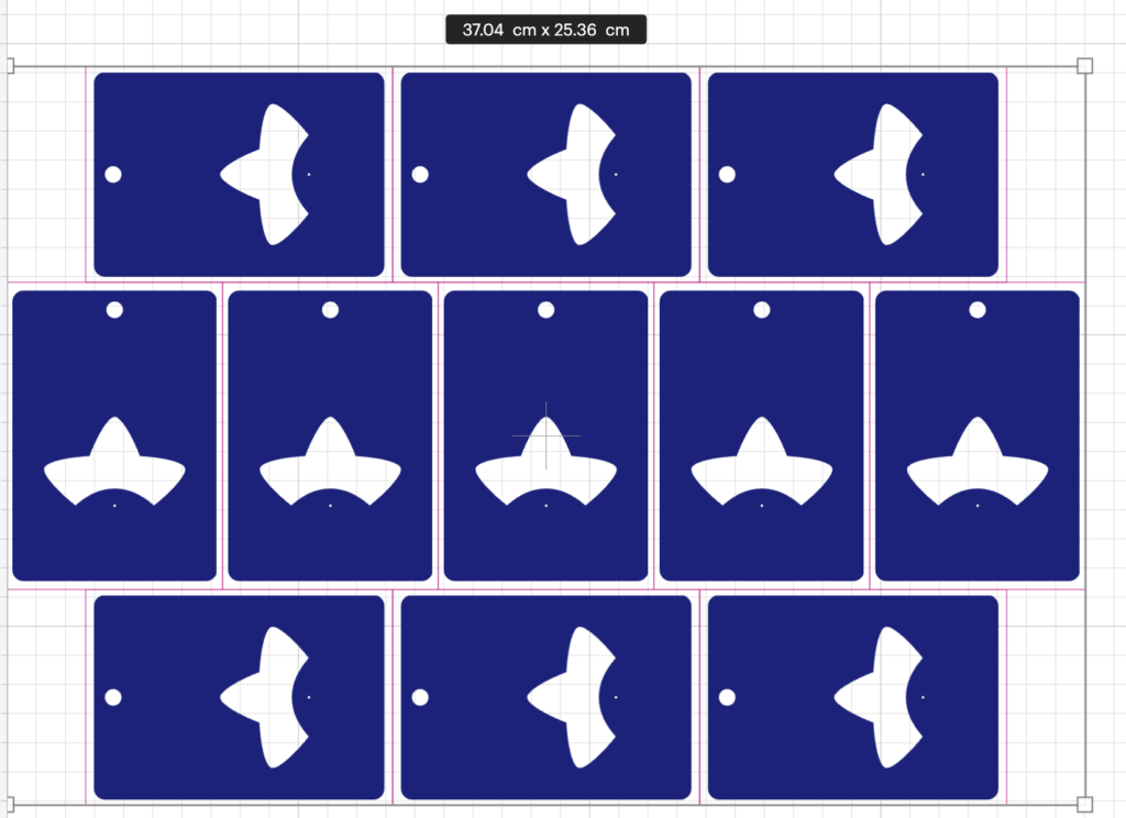
Let’s humour Cricut by scaling the offending design to its recommended size.
(I suggest also keeping a copy of your original design to the side, in case you want to make changes at the original scale. To prevent the app from blocking you from proceeding to the “Make” step, hide the oversized objects.)
Step 2: Print to PDF
Click the “Make” button to proceed to the mat preview.
Do not move the designs on the mat – leaving things in their default position makes for the easiest alignment if you want to exit the Make step and return back to it again. Click “Continue”.
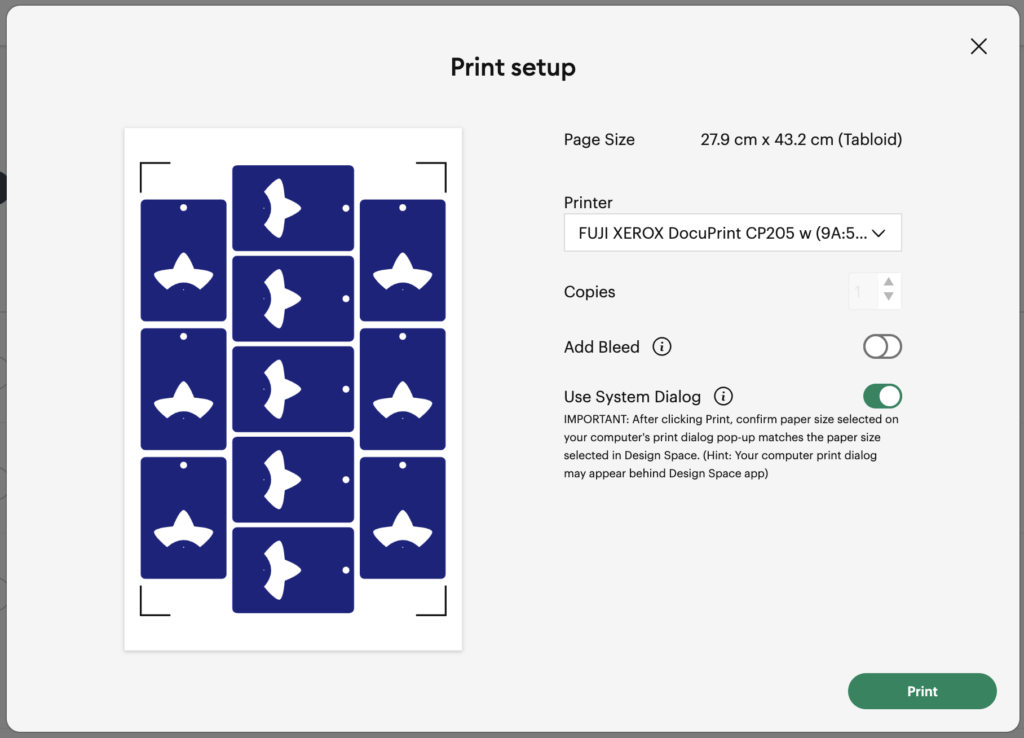
Open the “Print Setup” panel by using the “Send to Printer” button.
In this panel, select “Use System Dialog” to print your file to a PDF
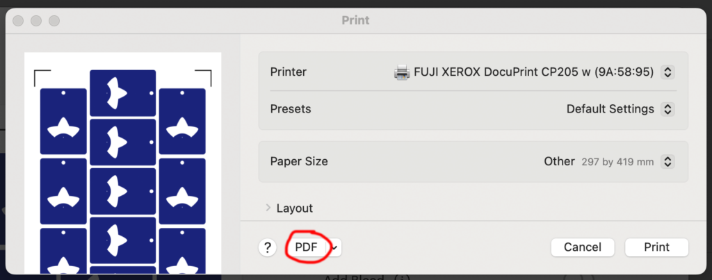
On MacOS, the print dialog always appears behind the Design Space app, so drag the Design Space window out of the way when the “Preparing Print” spinner appears. Now save your file as a PDF instead of printing it.
Step 3: Scale up the PDF
It’s time to do some maths.
We originally had a design that was 39cm on its long edge, but we scaled that down to 37.04.
That means we now want to scale this file up again to be 39cm.
39 / 37.04 = 1.05291576674
This is a little more than 5% larger, which so far I have been able to make work. I don’t know what the upper limits of this technique are.
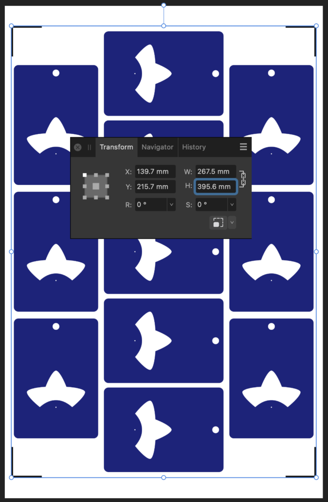
I’m editing the output file in Affinity Designer. The file that Cricut output has a long edge of 375.mm, so let’s type 375.7mm * 1.05291576674 into the H dimension field to get a new image of size 395.6 * 267.5mm.
While I’m here, I’m also going to set up my print graphics, allowing me to have better control of the bleed than using the normal Print & Cut workflow.
Step 4: Print
Print the file – I don’t have an A3 printer at home so I take my files to a print shop.
Step 5: Cut
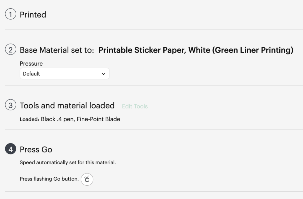
Back in Cricut Design Space, choose your material. (You may need to select “I’ve already printed” so that the app lets you do so).
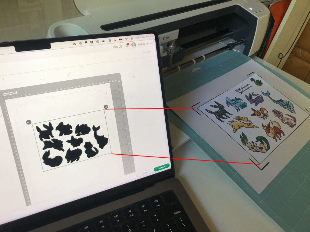
Affix your printed sheet to your cutting mat and load the mat. Press “Go” on your Cricut machine and let it do its cutting magic!
Another tip: If you’ve put graphics too close to the registration corners, you can temporarily place a sheet of white paper over them while the machine does its calibration. I usually just slide the white paper around by hand so I can remove it before the cutting begins. Coincidentally, the layout I’m demonstrating doesn’t use the edges so there’s plenty of “quiet” space to distinguish the registration marks from the artwork.
All done!
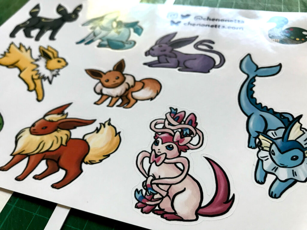
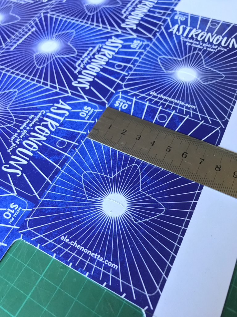
Here’s my cut pieces, at the scale that Cricut claimed I couldn’t have.
Actually, the vertical axis is a little bit off but this is good enough for my purposes and the bleed areas did their job. If I wanted to be a bit fussy about things, I would try moving around some of the cut lines, but do not move any cutlines that would change the outer bounds of the print, otherwise you’ll need to update your print file and recalculate its sizing too.
In summary:
Big Cricut wants to stop you from printing big. But follow these steps to break out from their boundaries!
Step 1: Downsize the design in Cricut Design Space
Step 2: Print to PDF
Step 3: Scale up the PDF (optionally, update any graphics)
Step 4: Print
Step 5: Cut
Please let me know if this guide was useful to you! Happy cutting!
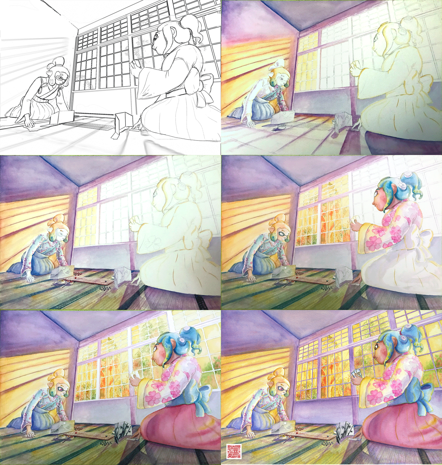
This blog post goes through a few of my Tableturf inspired artworks from 2023, ending with a quick timelapse of this painting:
With the launch of Splatoon 3 came a new game mode, Tableturf! I got quite into the idea of Tableturf, even being a part of coordinating an art collab project – Arty Siege – which paid homage to the in-game cards. I did lots of work for that – creating various design elements, having fun data merging artwork in InDesign, thinking about how the physical game would really play out, coordinating artists and creating artwork!
The art that I worked on included assets for the card backgrounds, and I illustrated one of the cards.
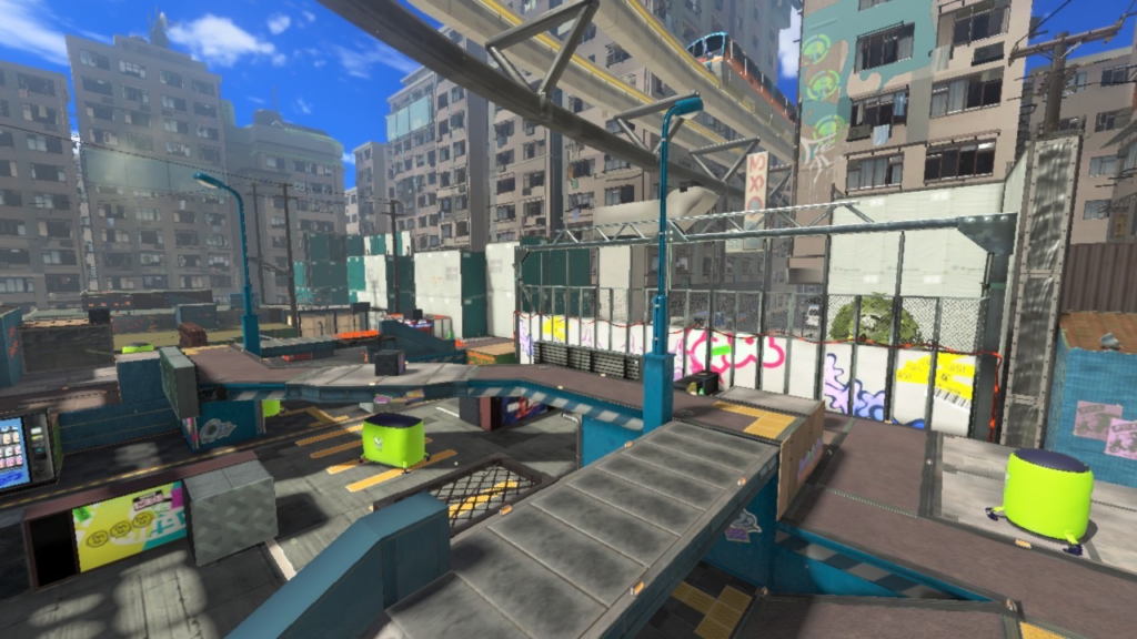
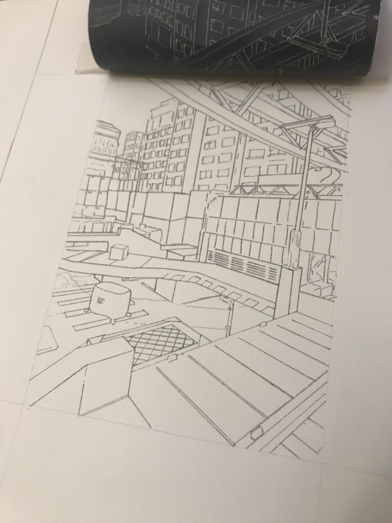
These background images were ink paintings traced from game screenshots. After doing a little photography tour in the game I exported the screenshots and used the Find Edges filter in Photoshop. I printed these reference lines to carbon paper and transferred them to watercolour paper.
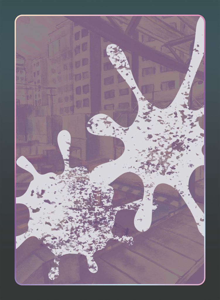
After scanning the ink paintings, I applied some gradient map adjustments to them to adapt them into the card background.
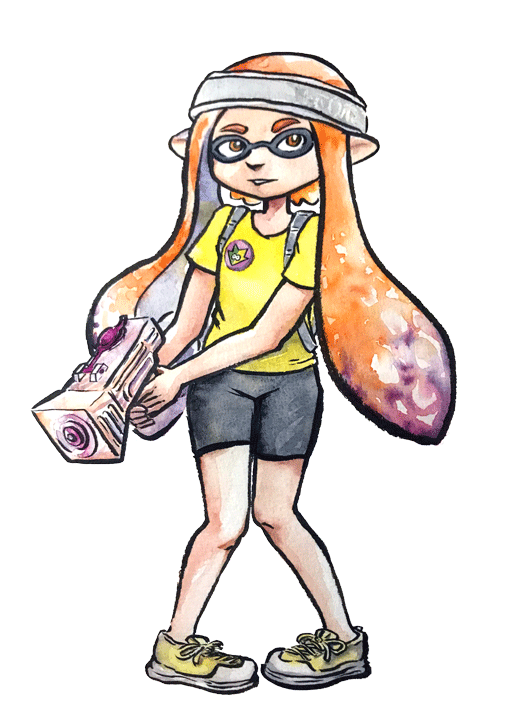
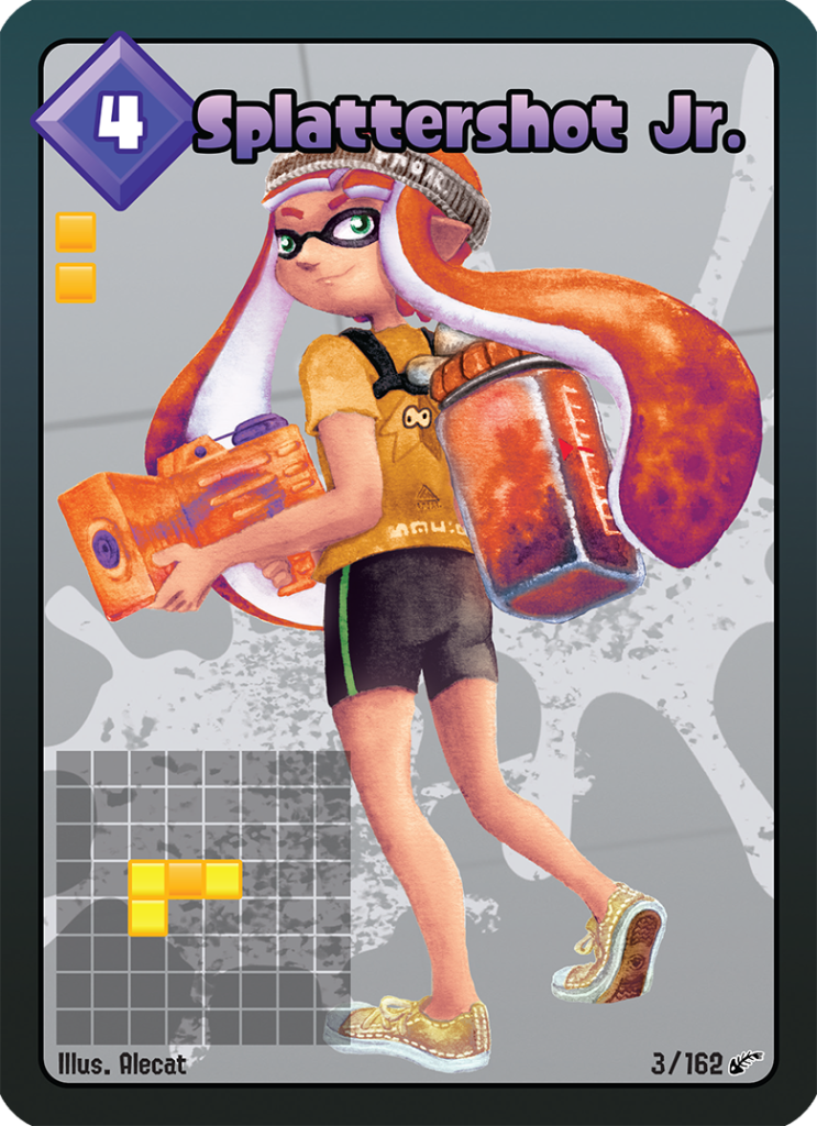
I chose to illustrate the Splattershot Jr. as my designated card for the project. I’ve drawn the newbie squid before and as a Junior player (I became a Junior main because of having to unlock kits on many, many systems) I just feel a certain connection to the default loadout.
During initial project advertising, I used this artwork. The pose is taken directly from the pose of the original Tableturf card. With this version of the artwork, I mocked up the first version of how the cards would appear, including tweaks to the card UI and creating a 3D view of the card.
My motivations for changing the UI were to make the Arty Siege cards distinct from the in-game works, but also to think about what would make sense for a real card game. The original cards put all their important information at their base, but I wanted to make all the pertinent information visible easily from a fanned out hand of cards. So I moved the grid and special costs to the left side.
I also straightened the alignment of the block grid. The angled grid was cool, and saved a little space, but I felt that when looking down at the game board and determining how to make a move, it was easier to visualise the move you wanted to play by having an aligned grid. Maybe that was just me, it’s not like things in the real world would be completely squared anyway.
Anyhow, relatively late into the project I started feeling a bit insecure about that version of the Junior being my entry into the project. I was surrounded by an incredibly talented pool of artists and felt like I needed to step up to the standards of my peers! I still like my original artwork but I also felt inspired by the work I’d done on the backgrounds to do a piece in ink and use gradient mapping to add colour.
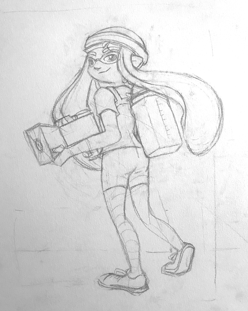
This time, I based the pose on some promotional artwork from Splatoon 2 – I wanted to show off the square ink tank because while the flat ink pack of Splatoon 3 features in some of the cards, many of the other ones seem to take cues from Splatoon 2’s fashion options.
Here’s the final version of the Splattershot Jr. card. Please do check out the Arty Siege website for all of the other works!
One of the things I did at the end of this project was to print out all the cards, which was a lot of fun! I felt like I built a new connection with each of the artists and their artwork in the process of printing, cutting and sleeving the cards.
While wrapping up Arty Siege I had a vague idea of running a promotional Tableturf tournament – maybe something in a casual vein, or with a bit of a team gimmick to allow a mix of player skills among drafted teams. The team angle was influenced by my favourite anime – Chihayafuru – a show that features a competitive karuta game based on the Ogura hyakunin isshu.
Chihayafuru is beautiful, and the way it depicts friendly competition really hits home. And there’s just something so great about the earnest enthusiasm of the players – they’re engaging in a pretty niche hobby so having the opportunity to play is something they’re truly grateful for. Coming from a grassroots Splatoon scene, I feel the parallels between the competition depicted in the show and some of my favourite times being a member of the Australian (and broader) Splatoon community.
Although I didn’t end up running a Tableturf tournament, the imagery and the idea for an art piece stuck with me.
As much as I adore Chihayafuru, I’ve never felt brave enough to try to tackle fan art for it. The gorgeous scenes, the sense of movement, the game that I only have the most superficial understanding of… it all felt quite intimidating.
But Splatoon, I feel comfortable in that universe…
(A universe which coincidentally seems to have a version of karuta already!)
However, my painting is not an attempt to retcon that karuta into Tableturf. In my headcanon, the two coexist. I just wanted to borrow the aesthetics of karuta for my Tableturf scene. I was inspired by the glowing sunset scenes of karuta which I associated with the characters practicing in the school clubroom, but also by the tournament games played while wearing kimono.
Before starting this painting I did two “mood studies” – just getting a feel for whether I could tame the contrast of yellows, oranges and purples before I started. Watercolour can be a tricky medium, and it’d be hubris to walk into this kind of endeavour without a plan.
That first image is sort of a Chihayafuru fanart, I guess – the scene is most likely Arata sitting alone with his cards – but that wasn’t the purpose of the sketch. I wanted to get a feel for how I’d depict the trees in the windows, and the light entering the room. The second sketch really sets up the composition that I’d ultimately use for the final piece.
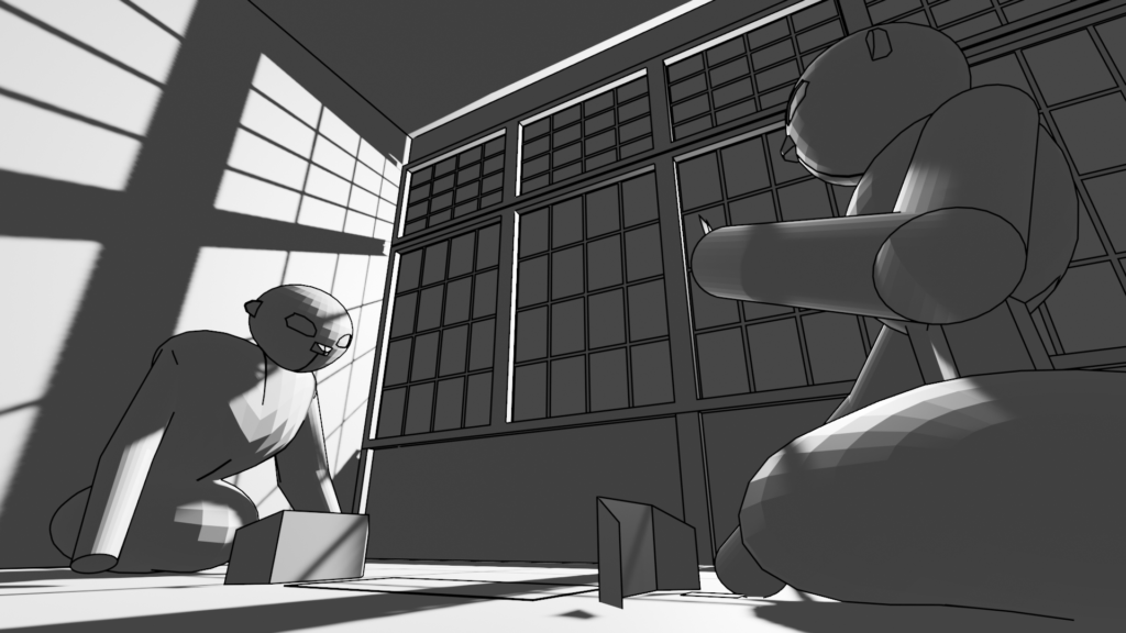
After deciding on that sketch, I made simple 3D version of the scene in Blender.
A digital sketch then filled in the character details
Which was then printed out and transferred to stretched watercolour paper, then painted over the span of a few weeks.
I also wrote a poem to go with this painting. It’s based on poem 77 of the Ogura hyakunin isshu. Here’s one blogger’s translation and writeup about the poem (I chose to highlight this blogger because they also have a post about the Karuta that appears in Splatoon 2!)
The translation included in that post is credited to Joshua Mostow,
Because the current is swift,
even though the rapids,
blocked by a boulder,
are divided, like them, in the end,
we will surely meet, I know
Swift waters parted by the jagged rocks are joined at river's end.
The overall mood that I get from this poem, having only experienced it through translations, is a mix of urgency and yet steadfast certainty that comes from love. Apparently, the “swift currents” were not in the original poem, and were a later edit, but I think the imagery is certainly much stronger with the idea of rapid waters.
I felt the scenario could be mapped quite closely to the energy and movement of Turf War, and by extension, Tableturf. The rapid currents can be whirls of paint instead, and the boulder standing in the way of the lovers could well be a grey block, created in Tableturf when both players play their cards over the same squares.
I chose to write my poem following the rough syllabic rules of the original poetry, the lines having 5-7-5-7-7 syllables. But I put a western poetic spin on them as well, making use of rhyme throughout.
Our rapid advance,
Blocked by chance or wit wherefore.
Must we halt our dance?
No - surge forth in this turf war!
We'll unite our ink once more.
The rapid advance describes that rush to claim turf, as well as for the rivals/lovers to meet at the middle of the map. “Chance or wit wherefore” refers to how the grey block ended up in their way. Was it coincidence that they played in the same tile, or was it cunning strategising from one of the players? With this obstacle in place, the shape of their relationship (whether it be a rivalry or a romance) is affected.
The ending couplet describes the characters choosing to rise above (or work around) adversity – in-game the boulders would not be passable at all, so they must certainly have some grit! Like the swift waters in the original poem, they’ll be sure to meet again.
I love how this artwork and poem came together. Reflecting upon them I feel all those warm fuzzy feels from all the ways that Splatoon – and more recently Tableturf – have made their impact on me. I’m grateful to have had another great year of art, friends and community and I’m looking forward to more good times in the future.
This will be my second Blaugust 2023 entry, pretend I posted it before midnight.
Some days I can craft from nothing to some pretty complex shapes, and then there’s days like today, where I spent four hours to make what is a laughably simple shape. But it’s setting up things for further progress, and if I’d balked in advance at the time I would be spending to get this step done, then I’d never finish the project at all.
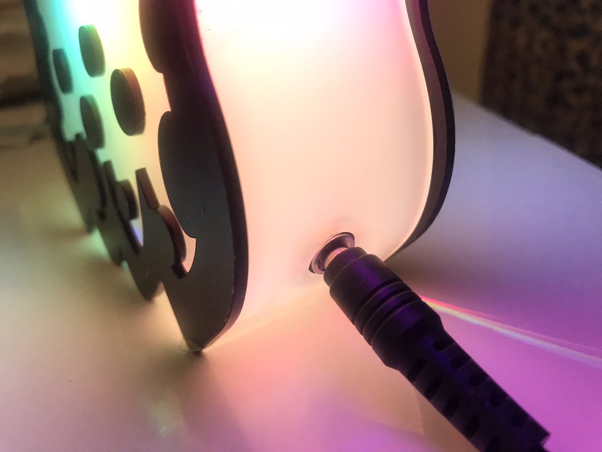
With any luck, I’ll have a new lamp design finalised this week, and this is the prototype of its socket.
Motivation
Oh no we’re jumping the shark really early this year if we’re talking about motivation on day 2.
There’s a lot going on this month, and I often find that having multiple interesting things on the go at once means I can bounce between them. I’m also aware that most of these challenges are self imposed so I’m not going to be stressing about missing any days. Still, it’s a fine balance between kindly letting myself off the hook once, and slipping out of the habits entirely.
Daily Habits
So, here’s something I’ve made no secret of – I cheat on some daily habits. I know that the sin of moving around the clock is worth it because losing a streak is demotivating, and the only person I’m cheating is myself (ok, maybe there’s people on the Duolingo leaderboards that would feel cheated but that’s really small change). And really, the accounting works out more favourably ultimately; by fudging the calendar a bit, I invest in the motivation for myself to get back on track the next day. This worked really effectively for my Ring Fit streak until two missed days in a row put a nail in its coffin. It’s extra hard to get back in the saddle after that… but I’m mostly sanguine about it now and about acknowledging that fitness isn’t a priority right now.
Anyhow, I’m backdating this blog post. And I’m going to be turning back the clock to do today’s Wordle. And hopefully I’ll return to both tomorrow with fresh enthusiasm.
Plastic backing piece – I used 2mm thick acrylic, cut to the size that I wanted the badge to be.
Brooch finding
Prepare your splash tag
You can screenshot your splashtag from Splatnet, but the resolution might not be high enough for a nice print. If have issues with the resolution, you can use the resources at https://leanny.github.io/splat3/collectibles.html to recreate the splash tag. The font files for the Splatoon 1 and Splatoon 2 fonts are handy for replicating the text.
After composing the splashtag, mirror the design.
Print it onto the clear film, and cut it out leaving a generous margin (at least 10mm) around the edges.
This design has been printed at 87.5mm wide by 25mm tall.
Assembly
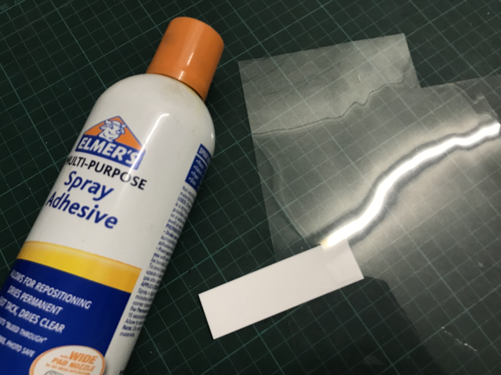
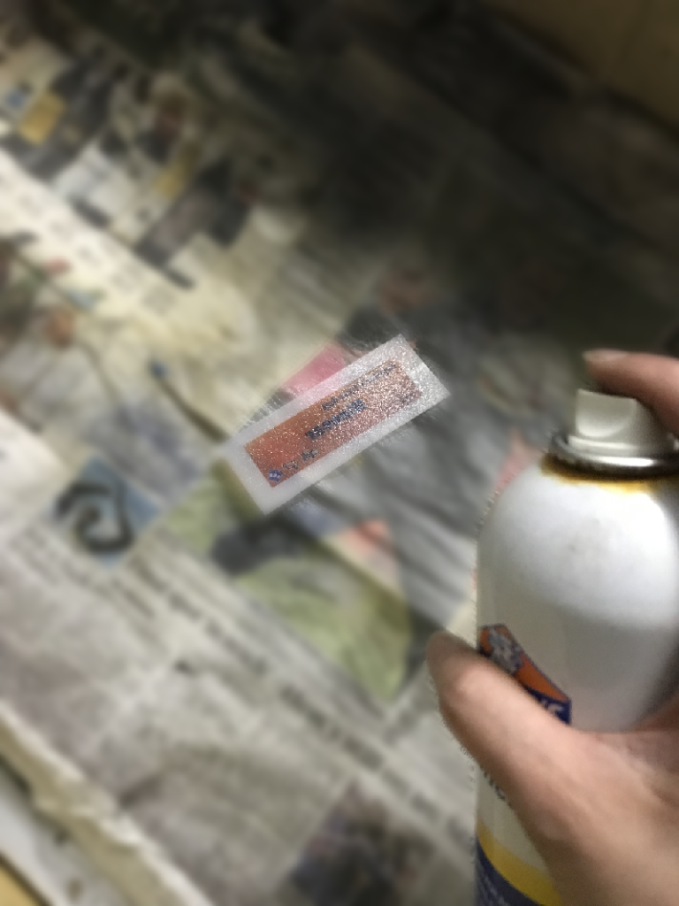
Apply glue to the the side of the sheet that you printed the text on.
Now align the transparency with the plastic backing and press them together. Make sure to only handle the extra margin of the plastic film so that you avoid smearing the glue on the splash tag itself.
It’s done! You can now attach a finding to the back.
Oh boy, let me take you down the rabbit hole that keeps sneakily stealing hours of my life from me.
We’ll start with a topic I’ve covered a few times before:
Seals
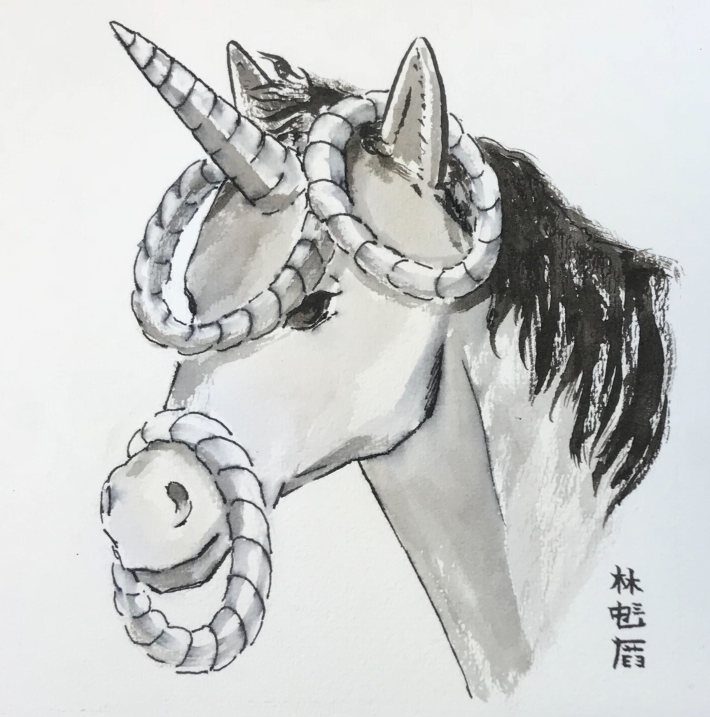
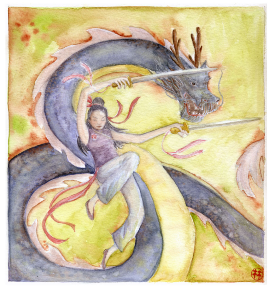
I’ve written before about my mock sinograph signature – a pseudo Chinese-character sequence that I use to sign my artwork with.
I have also signed my work in the past with a signature stamp that I picked up at a dollar store in Japan, that simply contained the character of my surname.
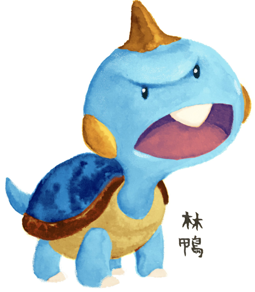
In the intervening times, I’ve experimented with laser engraving seals of my sinograph, and modifying its design. I briefly hit on a design I absolutely adored that incorporated “Alethea” into the character 鴨 (duck), which when put together with my surname 林 would have correspondingly given me “forest duck” as my signature. This would allude to the name of the chenonetta jubata in Chinese, nicely tying all of my identities together.
Unfortunately, a Mandarin-speaking coworker cautioned me against using 鴨 as a pseudonym. They informed me that when referring to people, “duck” is sometimes used as a euphemism for a male prostitute. So with that knowledge, I decided to fall back to my made-up characters.
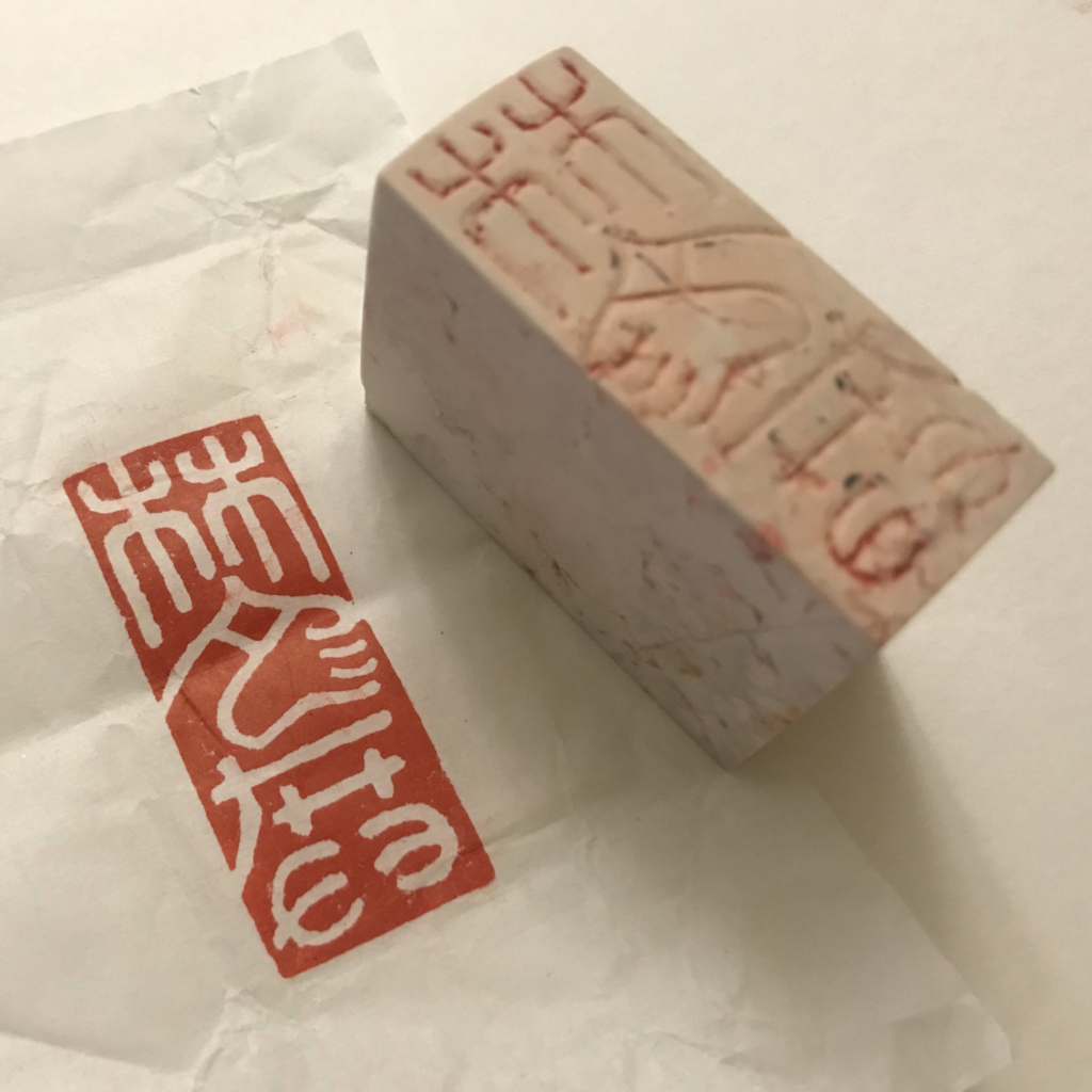
When I made the most recent revision to my signature, I decided to get it professionally carved into soapstone, and had the company confirm that I wasn’t going to run into any similar embarrassing misunderstandings with the design. The actual seal carving ended up being very expensive (considering I could have just laser engraved it myself), but I valued the peace of mind that came with having someone knowledgable vetting it. Experiencing how the seal design transferred so cleanly with good quality seal paste (the ink used to stamp the blocks with) also unlocked the next step in my journey.
QArt Codes
Some time ago, I read this blog post about embedding images into QR codes. As a tl;dr, QR codes are made to be tolerant to damage. Most QR codes that contain logos in them just cover the data contained in the code and take advantage of the error-correcting algorithm to ensure the right values are read out. “QArt Codes”, on the other hand, use a provided image to generate a URL that naturally encodes to something that resembles the source image.
I can’t remember what led me to the article initially, it was a looooong time ago. I may have been working on a puzzle hunt for AVCon that used QR codes to log people’s progress and I wanted to embed the AVCon Invader logo into it (so some time around 2014). But the puzzle hunt, and QR codes in Aus generally didn’t catch on so the idea just got relegated to the back of my mind.
Still, QArt codes are super neat and I’m surprised I haven’t seen them in the wild more. Actually, I think the page that generated the codes was down during the rise of QR codes in the pandemic, so there was a bit of a missed window. But the page is back now, and you can play with making your own! Or if you want to play with the code there’s a standalone version you can run locally.
(Side note, when I was researching game-parsing screen readers to work on Ikalog stuff, I ran into this blog post by Up Banking. That’s the only QArt code that I’ve recognised in the wild to date)
Adding 2+2…
This is the post that lit the lightbulb in my head.
I mean, having hit this point in my post it’s pretty obvious what we’re gonna do, right?
QArt Chopping and Changing
“So how did you lose hours of your life to this? There’s a page that generates them, you just put your picture in there and you’re done, right?”
Well, to start off with, as I mentioned above the page that generates them was actually not available for some time, so I had to mess around with the original QArt source code (with a few headaches) and then later had the fortune of running into the standalone version.
After that… I lost time to the search of perfection.
Here’s my first draft of a painterly QArt signature. The output of the QArt generator still had a lot of noise, so I used painterly brushstrokes to make the noise look more appealing. At this point I still only superficially appreciated the stuff in the article and while I knew about some areas that were more important to preserve than others I was mostly just drawing willy-nilly with the understanding that “QR codes can repair damaged data”.
It’s neat but it’s off-centre, it contains only my surname and it probably won’t scan properly when scaled down for overlaying on art.
I was satisfied for a while with the proof of concept, but later I started thinking about laser cutting myself a new signature chop anyway, as the soapstone one I’d purchased was too large to use on A4 and smaller art (the majority of my pieces!)
So I looked at the QR codes and realised that I should provide a source image that wouldn’t need to scale. I want to control the pixels of the code so I should provide a pixel art version of my signature.
This provides an okayish output – it’s a good basis on which to paint over parts to arrive at a more aesthetically pleasing version.
I did do some test runs with this kind of “corrected” design and to my delight they did scan when stamped.
However, I anticipate that the stamping process can be error prone and therefore it will be impossible to perfectly transfer the design. So I keep returning to these QArt codes to try to minimise the errors. First by lowering the amount of modifications that I make to the generated code…
Then, by changing the generation of the code itself.
One strategy was to reduce the area of the QR code that must be dedicated to my URL. I chose not to use a URL shortener. I intend to keep the chenonetta.com domain into the forseeable future but I can’t control what happens with any URL forwarding services.
I also opted to include the full http:// prefix in the URL. I did some playing around with readers and some automatically open pages if the URL starts with www. or ends with a .com but I didn’t want to rely on that behaviour. I kept the ale subdomain but that’s the least defensible decision and I might change my mind on it in the future.
So how to save space if I’m not shortening the input data? The original QArt coder uses byte encoding for the main part of the URL. This uses 8 bits per character. I modified the generator to create the URL in two parts – an alphanum encoded section for the main URL and then byte encoding just for the # that joins the URL and its throwaway anchor. Alphanumeric encoding uses 11 bits for every two characters. Overall I did still save a little space, even with the extra stuff needed to define the single-character byte encoded section.
I also played with manually specifying the masking strategy (the mask is a pattern that gets XOR’d over the generated QR code – read the original QArt code article for details).
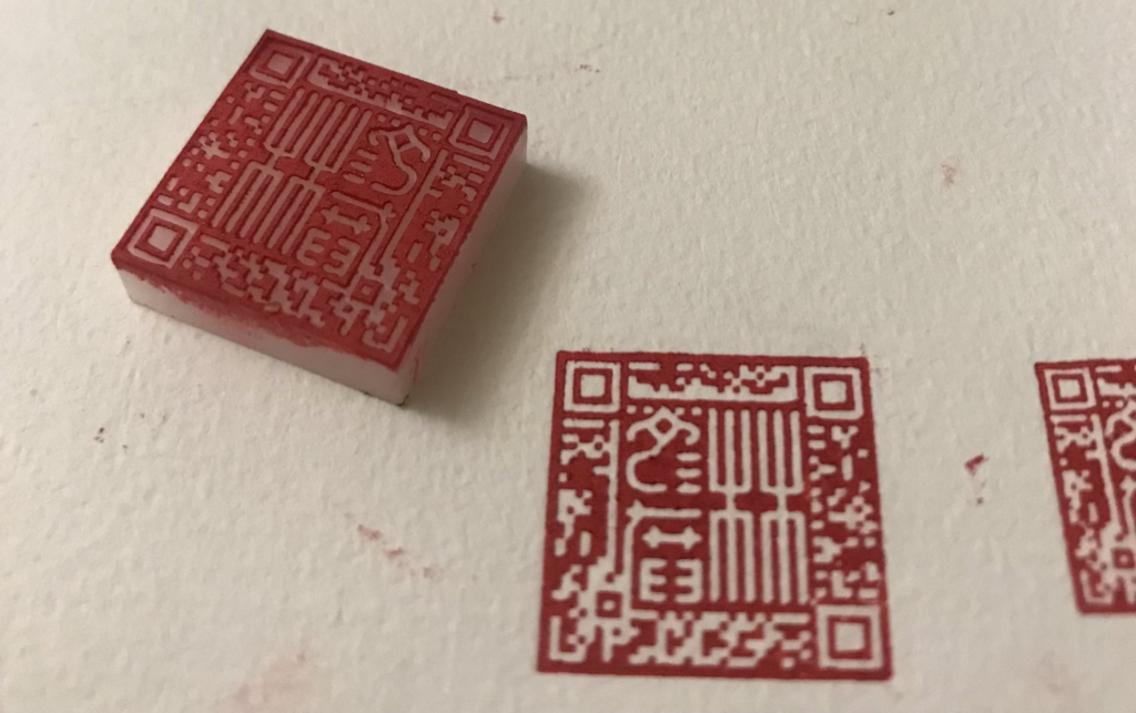
After a lot of iterating, this is probably the closest I’ll get for now. I think this is technically still a damaged code but the areas that I drew through are part of the instructions about how to read the code, not the data. Like the data itself, there are some redundancies for the instructions so the codes still scan ok. Most of the time I’ve spent on these codes has been spent in the cleanup and tweaking stages – what can I get away with without introducing errors?
This is supposedly an error free code according this debugging website – though the scale of the source image definitely affects its assessment of whether the code is error free or not. The site also doesn’t recognise flipped QR codes (even though other readers seem to be fine with them)
Being forced to make compromises on the final outcome always keeps me coming back to tweak things again and again – can I change the orientation so that I don’t have to use a flipped code? Can I rebalance the density of noise around the main design so that it doesn’t distract from the centre as much? Can I smooth the curves in the image more? I’ll just keep searching and searching for the ideal version of this design…
To wrap up, here’s the current setup I use for transferring the print to paper. I’ve been experimenting with moving to block printing ink instead of seal paste, because the latter is oil based and takes days to dry. So far I haven’t had a high success rate with the new ink but I think I’m learning. Sometimes a dodgy print can be recovered with a little bit of hand editing, though it requires some deft brushwork!
You’ll notice that these instructions are very sparse on images. At this time I have only completed the text of the guide. Even though the images will be necessary to make sense of these instructions I am providing them now as an incentive for me to return to finish this guide at a later date.
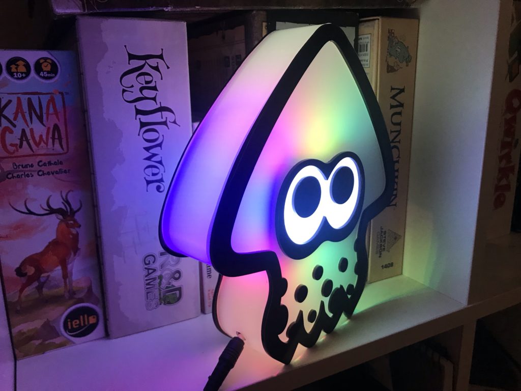
This is a guide to making a USB powered squid lamp, similar to but not exactly like the one pictured below.
If you would like to commission a fully assembled lamp, please email me at ale@chenonetta.com. Current pricing is $150AUD per lamp before shipping.
Components
I have included some basic price guides including shipping fees, but you can likely source some parts for cheaper! Prices are in AUD. Some of the links are affiliate links – using these to order your parts helps support me!
Used to illuminate the eyes. 1 metre will supply almost 4 lamps.
You could cut individual LEDs from the 100IP30 strip and space them out instead of buying this separate strip type. Filling the entire eye space with a 100IP30 segment is overkill so I use this more sparse strip as a convenience.
Heatshrink to fit over the LED strips (approx 10-12mm diameter)
Glue that can bond plastic to plastic.
I usually use SciGrip Weld-On 3, a water-consistency solvent that bonds very quickly, and SciGrip Weld-On 16 which is more viscous. Super glues will probably work fine.
Equipment
You will need access to the following specialised equipment. If you don’t own these yourself look out for your local Makerspace or tool library!
Laser engraving machine
Oven and/or heat gun
You could use your home oven but I prefer to use a dedicated crafting oven.
Soldering Iron
Assembly Instructions
Step 1: Cut the acrylic
Peel the protective paper from the back sides of the black and frosted acrylic. Leave the paper on the side that faces upwards while in your laser cutter. The paper will provide protection for the parts while we work on assembly.
Frosted parts file: DXF / SVG (Dimensions: 434×219.9mm)
Black parts file: DXF / SVG (Dimensions: 367.58×201.26 mm)
In these files red lines should be cut, blue and green should be vector engraved (ie, cut but with less power).
Blue lines should be a kiss cut allowing for the front protective paper to be peeled off. The green line should be a slightly deeper cut to assist bending of the tentacles.
Step 2: Glue the face plates
Peel the areas of the frosted pieces that correspond to black parts.
You should now be able to align the black pieces with the exposed frosted sections and glue them in place.
I apply the Weld-On 3 by dipping an old paintbrush into the glue. I then touch the wet paintbrush to where the two pieces of acrylic meet and the glue is drawn into place via capillary action. This creates a strong bond within a minute.
⚠️ Wear appropriate PPE when working with solvent glues. Nitrile gloves, safety goggles and a respirator are recommended.
Step 3: Bend the side walls
Preheat your oven to 160°C
Peel the protective paper off the rectangular pieces of frosted acrylic. If left on, these pieces would leave sticky residue on the parts as we bend them.
I recommend working on one piece at a time. Place each piece in the oven and let it sit for about 5 minutes. It should be floppy when you pull it out. If the piece forms bubbles it has sat in the oven for too long.
Form the pieces into shape using the black outline of the face plate as a guide. You’ll be using the long piece to form the top head of the squid, the two identical pieces to make the left and right tentacles and the shorter piece with the groove in the middle of it to form the middle tentacles.
If you cannot fit the full length of the piece into the oven at once you can first bend it by heating it with a heat gun or by placing the piece in the oven with the door open so that half of the sheet can be bent.
If you don’t have an oven that you feel comfortable placing your acrylic into you can heat your pieces using a heat gun. You’ll need to work slowly, bending in sections rather than forming the full shape in one go.
⚠️ Wear heat proof gloves when handling the hot acrylic!
It can be difficult to bend the sheets correctly. I have included some files for jigs that can be cut from 3mm MDF.
To use the two-part jigs, rest the hot piece of acrylic against the bottom piece, then press the top piece into it to create the indentations.
The large jig is designed for the long piece of acrylic to be wrapped around it. Hold the ends in place so that they cool without expanding outwards again.
To speed up cooling of the piece, you can wave the pieces in the air so that cool air passes over them quickly, or blow cool air across them.
Step 4: Cut the socket hole
This guide assumes that you’ll wind the USB cable through a hole in the side of the lamp.
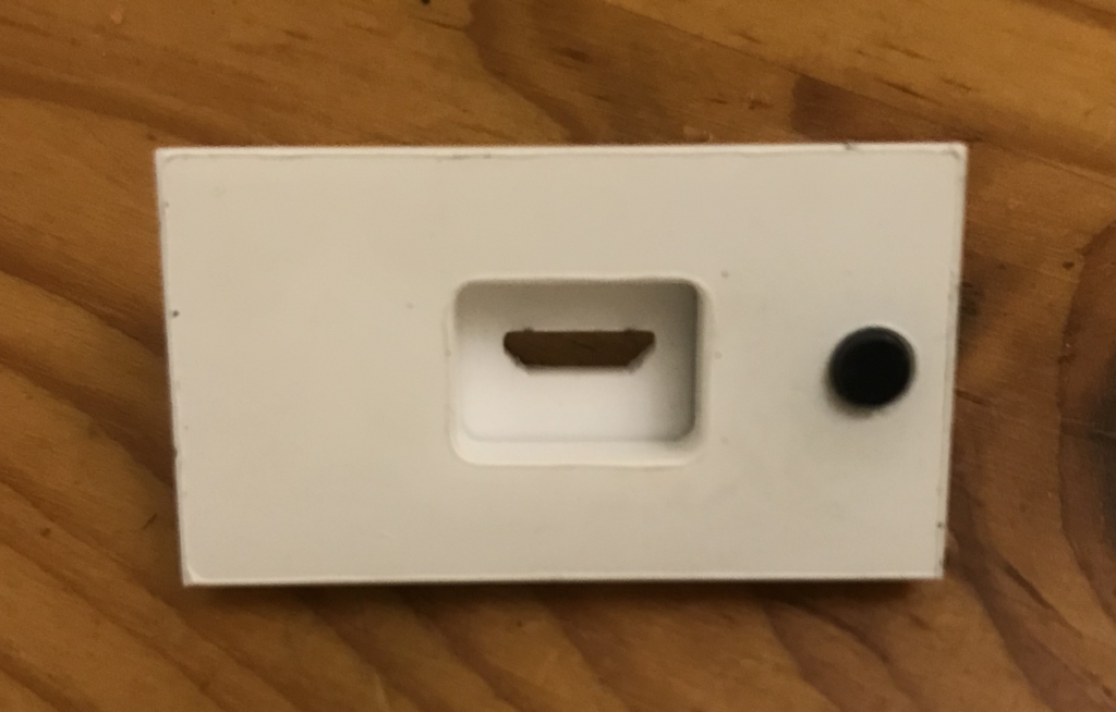
There are alternatives (my current lamp design provides a micro USB socket on the outside) but they’re complicated enough that I won’t go into them in this document.
Options:
Drill/cut a large hole in the side big enough for the whole micro USB cable to fit through
Cut an approx 5mm diameter hole then bisect the piece through the hole
The option you pick will depend on which aesthetic tradeoff you prefer. For 1, the large hole will cause the insides of the lamp to be seen from some angles. 2 will have a visible line across the wall where the piece was split into separate parts.
Step 5: Glue the sides
One of the face plates has a slot in its tentacle. Place it face down (with the black acrylic on the bottom, and the frosted on top).
Glue the walls of the lamp to the edges of this piece.
If you cut the side tentacle in half in the previous step, then remember to feed the USB cable through the hole before gluing the walls in place!
Step 6: Make the eye sheath
The eye sheath holds the two plates of the lamp together without any glue! It also holds the LED strips, allowing for beautiful illumination of the edges of the lamp.
Cut a length of 1mm boxboard to 38x265mm. I recommend cutting the long side against the grain – you want to be able to easily bend the long loop. This video explains how to find the grain of your sheet.
Mark two parallel lines 14mm away from the long edge. This marks a 10mm gap in the middle to align your LED strips to. Flip over the piece and mark lines on the opposite side, too.
Line both long edges of the piece with masking tape. The tape protects the edge of the cardboard and provides friction when inserted into the squid’s face plates.
Bend the cardboard in half, then slowly curl the cardboard in the opposite direction of this bend. You are aiming to make the shape of the eye mask of the squid.
It can help to slot the piece into one of the face plates as you work. There should be about a 3mm gap between the ends of the cardboard.
Join the loop with a piece of masking tape on the top and bottom, leaving a gap to allow the LED strip to pass through.
Step 7: Make the LED strip
When working with addressable LEDs, take note of the arrows denoting the direction of the data line.
Start of strip ➡️➡️➡️➡️ End of strip
Cut a length of 100IP30 strip to 26 LEDs long (26cm) – this piece will be called Segment A from now on
Cut a length of 30IP30 strip to 8 LEDs long (approx 26.6cm) – this piece will be called Segment B
Cut a piece of heatshrink, 1-2cm long
Slide the heatshrink over the start of Segment B, and push it clear of the solder pads. Align Segment A and Segment B, making sure to double check the direction of the data line and that the correct terminals are in contact.
The 5V, data and G pads of each segment should meet their corresponding pads on the other segment.
The arrows should face in the same direction, with Segment A leading INTO Segment B.
After joining the strips, pull the heatshrink over the join and shrink it there, providing protection for the connection you just made.
Solder power, data and ground wires to the start of Segment A. These should be about 7cm long.
Once happy with your wire joins, you can shrink a 1cm piece of heatshrink over them for protection.
Step 8: Attach the LED strip to the eye sheath
Crease Segment A after the 13th LED by facing the LEDs towards another and pinching the cut line.
Peel the backing off of Segment A and nestle the crease that you just made in the halfway fold of the eye sheath, lining up the strip with the guide lines you drew on earlier. Now stick down the sides of this segment, taking care to stay between the lines as you wrap the strip around the cardboard.
Feed the end of Segment B into the gap in the eye sheath and bend the heatshrink-covered area back over itself. You can now remove the adhesive from the back of Segment B and affix the strip to the inner face of the eye sheath.
Step 9: Prepare the controller
Connect the Wemos D1 mini into your computer using a micro USB cable. Install WLED to the controller at http://install.wled.me/
Desolder the LED on the board – otherwise the blue light may interfere with the appearance of your coloured LEDs.
Desolder the Reset button (optional – depending on how you orient the controller it may be more likely to bump the reset button accidentally).
Solder your wires from the LED strip to the adjacent 5V, G and D4 terminals. Take care to connect the correct leads to the right terminals! The LED strip has the 5V and G lines on opposite sides, while the Wemos has 5V and G next to one another.
If everything has been done correctly – plugging the D1 into power will light up 30 of the LEDs on the strip in an orange colour.
Step 10: WLED settings
Connect to the WLED Access point. Default SSID WLED-AP, password wled1234
If you have a favourite preset, you can specify it as the startup pattern on the http://4.3.2.1/settings/leds page.
If you’ve connected WLED to your home network, replace the 4.3.2.1 with the IP of the lamp. You can find the IP address by checking the list of devices on your router, or by installing the iOS or Android WLED apps and searching for devices.
Step 11: Enclose the lamp
Slide the Wemos controller into the slot in the frosted acrylic. This slot provides a snug home for it to stay in the lamp and hides a lot of the shadow that would be cast by the controller.
Check that the cardboard eye sheath is smoothly bent and slot it into the body of the squid (the face plate that you’ve attached the walls to).
The other face plate can now be fitted over the eye sheath. You may need to jiggle it somewhat for it to fit snugly. Be patient and feel for how the cardboard fits into its slot. Once it’s in place the black border of the face plate will be flush with the walls.
Optional: Before attaching the face plate, line the walls of the squid with double-sided sticky tape. This provides some additional adhesion to hold your lamp together while still providing the option to reopen the lamp in the future if you need to do maintenance.
Now that lamp is fully assembled you can remove all of the protective paper! It’s done!
Closing Notes
There are a few differences between the lamp in this guide and the lamps I am currently making. Incorporating the below changes are left as an exercise for the reader
The power port. My v4 lamp includes a micro USB socket on the side, instead of threading the cable through the side of the lamp. I also take the 5V power from this socket instead of from the 5V pin on the Wemos D1 Mini, allowing me to set a higher current limit in the WLED settings.
This guide advises permanent solder connections instead of temporary connectors. I’ve used connectors like the JST XH2.54 (Dupont connectors would also work) to allow me to swap various parts in and out – this can be good for making and testing many lamps at once or for replacing a single module of the lamp if it is damaged.
At the time, I was running Splatoon LAN events and I thought to myself…
What if… I made squid-shaped lights to match the player icons that appear at the top of the screen during gameplay?
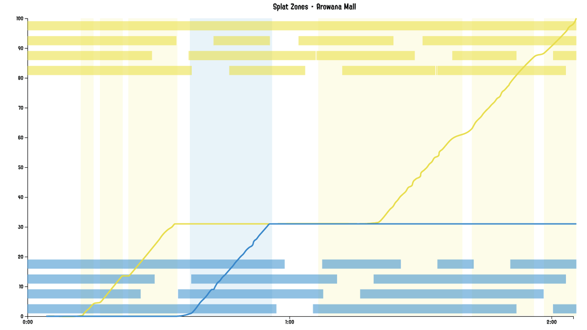
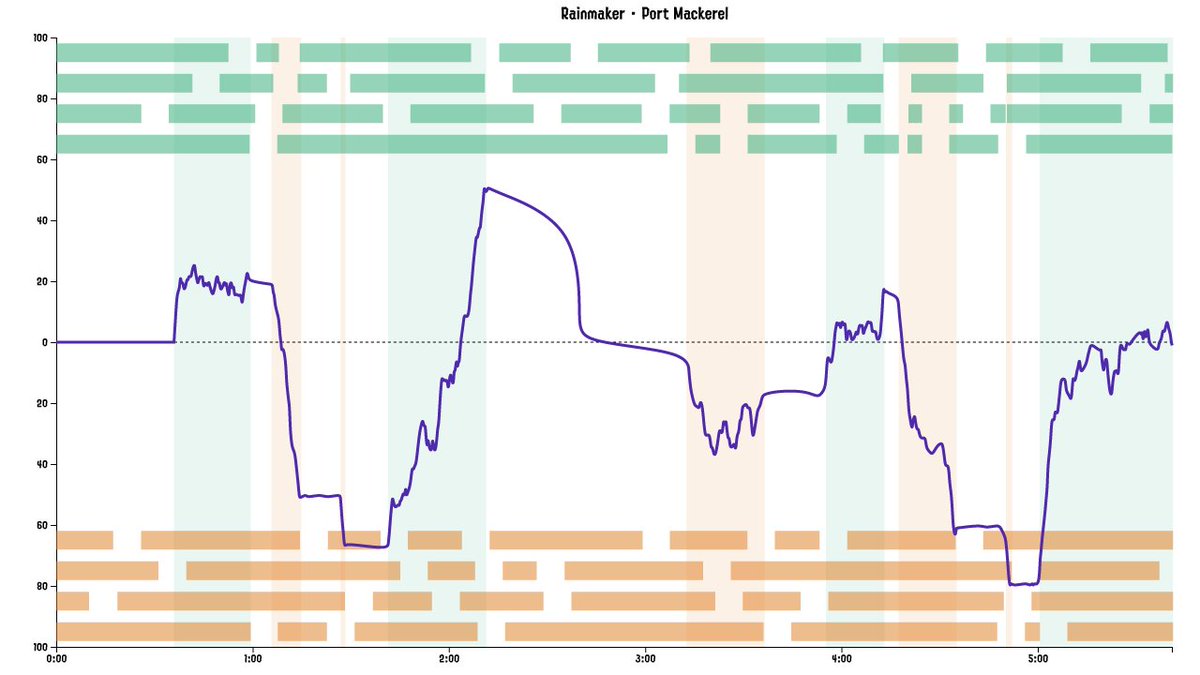
What if… I also combined it with the uptime tracking code in Ikalog to dynamically change the status of each light based on whether a player was active or splatted?
Then at a LAN, we could have a light stationed in front of each player to emphasise what was happening to them throughout the game!
Then I did nothing with the idea. Every few months I’d longingly watch DIY RGB panel videos on YouTube before getting stuck on deciding how ambitious to make the build and then moving onto something else.
Motivation
When Splatoon 2 came out it set the idea back a bit. Ikalog didn’t receive any updates beyond the Splatoon 2 testfire. In particular, the code to track player uptime in Splatoon 2 needed some creative problem solving; the icons change size based on the game state, making it harder to get a lock on them to determine their correct state. In September last year I did get a version of the tracking working. (I might write a separate blog post about some of this?)
Somewhere in my brain, the Splatoon RGB Light project itched, but it wasn’t strong enough to pull me away from the other projects I was tinkering with at the time. I wasn’t going to be at any LANs for the foreseeable future, so was there any point?
Then, a year later, my dad was working on some lamps of his own – beautiful, intricate wood-carved pieces. I took the opportunity to throw together a nightlight to use with his LEDs.
I literally did the designs for the nightlight on the bus, and had it cut and assembled within an hour of getting home.
It was so simple and effective that I got thinking again about the Splatoon light panels. Even if I didn’t get the gameplay integration working, they were going to look cool on their own!
Lamp Design
Before making 8 (or 16, to include Octolings) light panels, I thought I’d start by making a single freestanding lamp, to test the light transmission and generally get a feel for the components involved.
What is a light box made up of? It’s simply a light source with a diffuser. A little distance between the light source and the diffusing material allows the light to have an even glow.
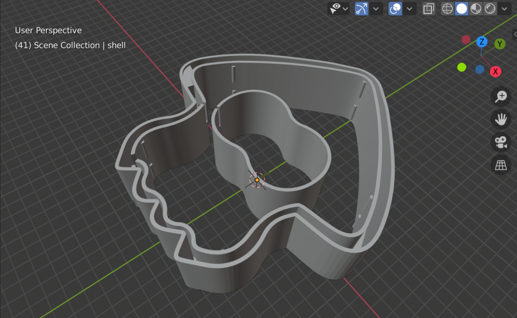
My original mockups for the lamp was a double-shelled container. The RGB light strip would run around the inner perimeter and then pass into another light-blocked area for the eyes, and the space between the two shells would provide room for electronics to be hidden. I ordered a 1m length of WS2812 lights as the light source.
While I have a laser cutter that allows me to cut pieces to accurate size, this design required curved shapes. I contacted 3D Prototypes And Models and Dan quoted >$100 for the printing. The large perimeters being printed up to 5cm tall resulted in an estimated 14 hour print job.
“Ok,” I thought, “I’ll drop the walls to 4cm. I’m willing to pay for one print, maybe I’ll just make the one lamp and end the project there.”
But then I started mocking up how the lamp would look and it felt… too small. I scaled up the design as far as I could to use the full meter of the LED strip. Well now it’s gonna cost even more to 3D print the shell and might be too large for the 3D printers available (not really, but I was starting to look for an excuse to not spend the money on 3D printing when the end goal was to make a number of these things).
Plus, Dan advised that the honeycomb structure of the 3D print would likely show through any illumination from inside the lamp. It was time to tackle things differently…
Acrylic Bending
I have been wanting to experiment with acrylic bending for a while, but the right opportunity hadn’t presented itself. I hadn’t seriously considered it for this project because it seemed too cumbersome to try to accurately bend the pieces. But then I found this video, where the side walls of acrylic lettering was hand-shaped using a heat gun, and I realised this was pretty similar to what I would be trying to achieve.
I asked to borrow my mum’s heat gun, but while waiting for her to dig it up I also had thoughts about making a DIY acrylic bender, or maybe heating up the acrylic in an oven.
Side Story: Toaster Oven
I had a toaster oven that I’d bought second hand to bake polymer clays in (I bought the oven from an older lady named Alethia who did a double take when I responded to her Gumtree post). But after just a few projects the oven had gone unused. So after many years, when I decided I wanted to use it to bend acrylic, I plugged it in and… it tripped the safety breakers in our house.
Tried again, tripped again.
Ok so the toaster oven is bust. Or is it?
I Googled and… there was the suggestion that maybe moisture had built up in the ceramic heating elements, and this was leading to ground leakage. Suggestions to dry them out? Use a hot air gun (still didn’t have mum’s on hand yet) or run it without RCD protection so that it would self-heat and dry.
I looked at the “No RCD” switch under my stove and decided – yeah nah, I better have someone with a little more expertise take a look. After all, did I really want to trust Dr Google with this diagnosis?
So I ended up at the Adelaide Repair Cafe, hosted by Makerspace Adelaide. The lovely folks there helped me to disassemble the toaster oven, to validate that ground leakage was indeed the problem, and to check for any internal corrosion or damage.
One of them did suggest the moisture issue with the elements – based on his own experience of working in physics labs where the equipment would regularly have these issues after going unused for periods of time. So we ran the toaster oven without ground protection and after about 15 minutes it was good to go.
Repair Cafes are great. A fantastic free service to breathe new life into things to save them from landfill – I was so delighted I volunteered to help at their future monthly events.
With that little Sunday afternoon adventure done, it was time to create the full squid assembly!
Structure
By now I’d been able to experiment with the RGB strip and the front and back plates of the lamp.
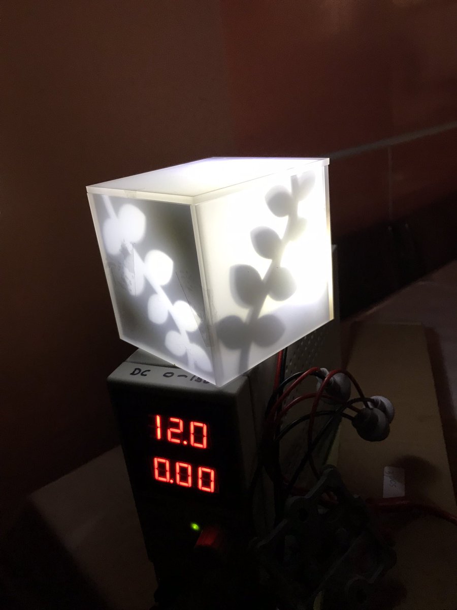
The plates are made from frosted and black acrylic. The black outline has been modified slightly from the original Squid design to allow for the lamp to rest on the tentacles without tipping to the side.
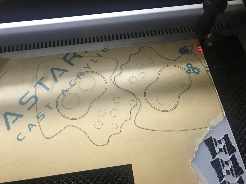
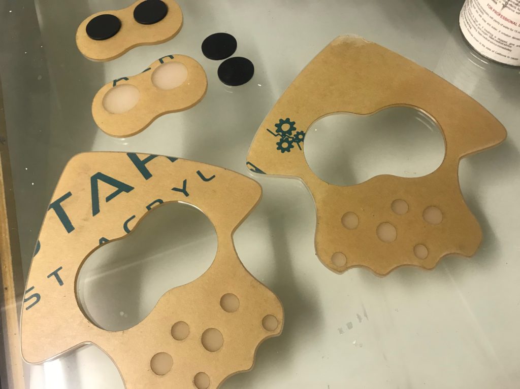
When cutting the frosted acrylic, I kiss-cut the outlines of where the black would be glued, so that I could find the right positions to place them. By weeding out only the areas where the black will be glued, it also reduces the risk of the frosted acrylic being damaged or marked during gluing and other construction steps.
By cutting the eye shape out of the middle of the frosted sheet it leaves a gap that can snugly hold a piece of cardboard. This cardboard serves a few different roles. Firstly, it is the mount point for the white LEDs that will illuminate the eye area. It also blocks the light that white light from blending into the rest of the lamp, and vice versa – keeping the coloured lights from bleeding into the eye area.
Because the cardboard is a tight fit, the two two faceplates can be held together by the cardboard only – and without any of the outer frame being added. Even in the final version of the lamp, I leave one faceplate unglued for easy future opening of the lamp.
This first mock-up of the barrier around the eyes is a bit messy, but for the final version I bent the cardboard along the grain so the curves came out nicer. The edges are also covered in tape to help with fitting into the gap in the frosted acrylic.
After recording the above video, I decided that I could also put the coloured lights on outside surface of the cardboard wall. This meant that I no longer needed the shell to hold the light strip, and with the light being directed outwards… why not allow it to also shine through the outer walls?
So my plan of bending 2mm black acrylic – which would be both easier to bend because of its thickness and (maybe) also because its colour would more easily absorb the heat – became a plan to bend 2mm white acrylic. But that didn’t transmit the light to my satisfaction.
The 3mm frosted (same as the front and back panels) became the goal. I decided to bend the acrylic in 4 segments, to avoid sharp corners. One for the ^ of the squid head, one for each of the sides, and a single curved piece on the base of the lamp, avoiding the pointedness of the individual tentacles.
Forming the Plastic
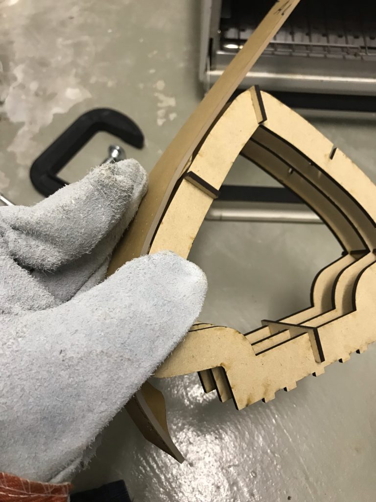
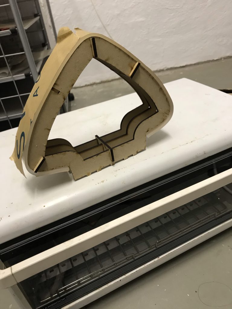
I made jigs to help form the heated acrylic. My first attempts to bend the acrylic over a jig didn’t work out well because the my gloved hands had trouble guiding the acrylic into the right position. So I added walls to the jig to hold the acrylic. I also added a guide to align the top piece into the bottom piece when pressing the halves together.
For the smaller pieces, I placed the bottom piece in the oven together with the acrylic piece to heat together. Annoyingly, this would affect the fit of my MDF pieces – the MDF would change shape in the heat and the joins would go loose. But other than this, the jigs were pretty effective – provided the acrylic was able to get soft enough. (“Soft enough” seemed to roughly correspond with “when the assembly appears to be smoking” but I need to find a better metric because fire and noxious fumes = bad).
The large piece over the squid head was a pain because it was too large to fit in the oven. I heated it from the ends with the oven door open and slowly it was able to bend enough for me to fit the whole thing in. A light etch in the middle of the piece allowed me to align it correctly with the jig.
The pieces aren’t bent perfectly, but they’re good enough. I glued them to one of the faceplates and the basic lamp is done!
Circuitry & Software
My LED controller software is wled – run on a Wemos D1 Mini, an ESP8266 board.
wled’s built-in colour palettes and effects are perfect for this use case, and it has a JSON API that I can use push updates from IkaLog if I ever get that integration going.
I chose a 5V LED light strip so that I could run the D1 on the same power source. The lights use 18W per meter and the plan was to use 1m per squid so I sourced a 5V 4A power supply. I didn’t use any logic shifter or resistor in my circuit… probably should, though.
I forgot the data line on the LED strip is directional when I did my first cut-up-and-resolder – which I could have gotten away with without realising if I’d happened to get it right.
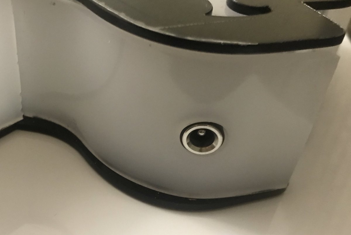
The socket fitting was mounted low and centrally, so that the wires coming off it would not be visible through the frosted acrylic. The hole for the socket was cut after the acrylic was bent, and I cut a clear “washer” to affix it to. The end result is a socket that sits nice and flush with the wall!
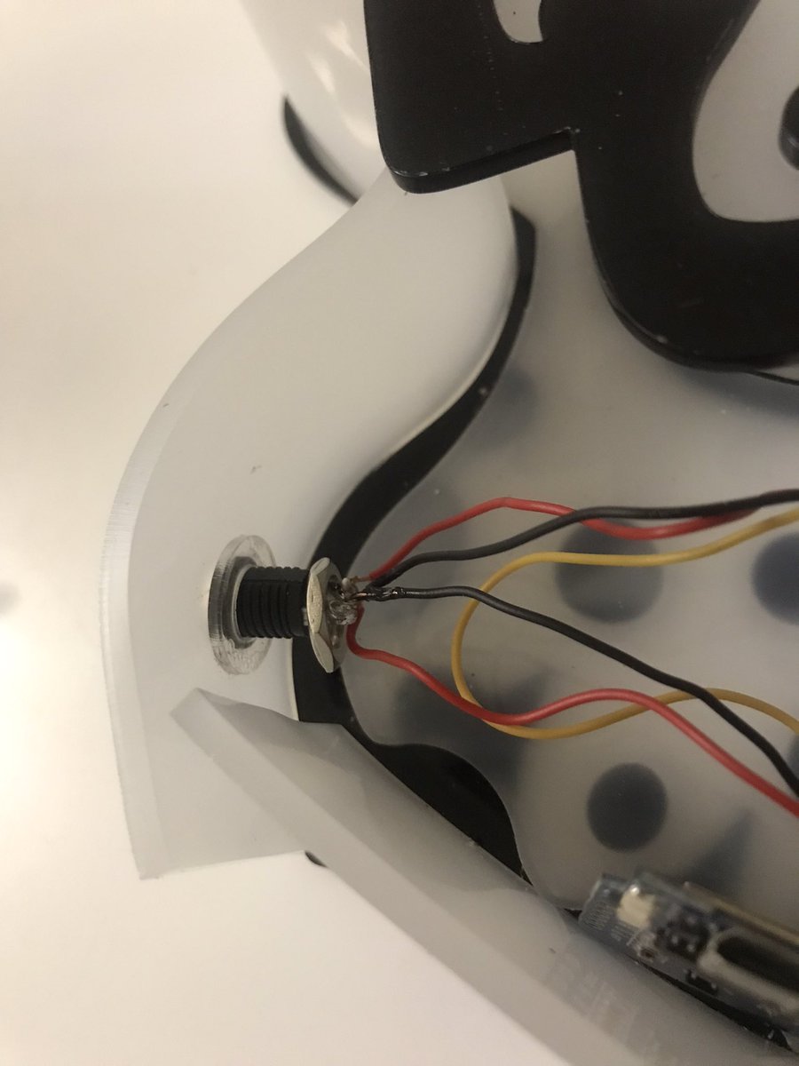
Unfortunately, in the process of doing the final wiring and soldering… this happened.
Can you tell what the problem is? When trying to buy a bit more space to move the parts around, I unfastened this nut. Then once everything was reassembled I forgot to screw it back, and with the power plugged in the nut created a short circuit.
I fried most of my LEDs from this mishap. I salvaged a few unused ones and hey the lamp still looks… ok with partial lighting, but that’s the reason why the photos at the top of this post have a dark patch across one side.
In The Next Episode…
Thoughts for future builds:
Maybe I don’t need that extra loop of LEDs for extra brightness, it actually looks passable with only 12 LEDs (apart from the missing corner). Plus the original idea behind using three loops was so that I could provide data from either end – but that’s moot when the data line is directional.
I need to find a way to make the wire connections without needing to permanently solder things down. Manoeuvring in limited space when everything is stuck together is a pain. Even when we took apart the toaster oven, those connectors had slide on terminals… maybe I need to do the same. So spade connectors, LED strip coupling and header pins on the D1…?
To do the full 4v4 team light panel build, I think I’ll move to a 12V LED strip so that I can chain multiple panels off the same power supply. Using 12V LED strips will require extra components to step down the 12V that will power the LEDs to 5V for the the D1, as well as a logic shifter to convert the 3.3V data line to 5V (I’m getting away without a logic shifter for the 5V LED strip but it sounds like one will be needed for a 12V strip.)
Oh gosh if I do want to get that game integration working I should probably work on that code now before any Splatoon 3 footage appears and affects my motivation again…
Blaugust 2016 is starting and I’m probably the least prepared that I’ve ever been for it. Considering that I’ve needed utmost coordination to be able to pull off Blaugusts in the past, this makes me rather uncertain about how I’ll be managing for this one.
As I look back on my posts from Blaugust 2015, I can see that a lot of what I’ve been doing in the last year has been an extension of what I achieved back then. A lot has changed for me personally and professionally in the time between Blaugusts and I guess now’s as good a time as any to reflect on it all. That’s right, once again Blaugust is encouraging me to explore new grounds as I make an actual diary-like post on my blog.
Work
In November last year my work transitioned over to a new employer, a single-application focused company which was started in Adelaide but is now headquartered in San Francisco. It’s been a great experience, though sometimes challenging working in a remote capacity to most of the team. Our local office has since doubled in size and it’s nice to have more people around than just the three of us.
I work a lot now on front-end web stuff. I like it, but I hate all browsers.
Laser Cutting
I receive jobs every now and then to cut jobs on my laser cutter from a friend that runs a 3D-printing based business. There’s a mix of clients being directed towards me as well as cutting components for pieces he is assembling or incorporating into other works. At the end of uni semesters a deluge of architecture students are sent my way, needing assistance completing their university assignments.
When I first bought the laser cutter I entertained thoughts of spinning it into a fulltime source of income. I’ve actually got a rough balance sheet that shows I’ve covered the costs of the machine with the various cutting work done on it as well as art stuffs I’ve been selling over the past two years. This feels like a huge achievement, and I’m very proud of managing it so quickly. However fitting in the time to do the jobs alongside the day job has been exhausting. I do not see a path to transitioning to doing such stuff full time, and nor am I sure anymore that I would actually want to.
Art
Doing more work on the laser cutter has come at the cost of pursuing much of my watercolour work. Actually I guess I’d been lax even prior to getting the machine. I struggle to find the motivation to sit down and create sometimes, other times I struggle to brainstorm things to paint.
But I do feel that even if it’s a slow pace, I’m still learning and expanding my watercolour skills. I’m not dissatisfied with how things are progressing.
Chenonetta Creations
Slowly over the last year I’ve been defining out what my little artistic niche in the world is. It is only natural that I’ve been putting together laser cutting and watercolour techniques to create what I hope are unique works of art that reflect my skills and personality as an artist. Along with this, I’ve been slowly expanding out my spheres of social media presence, the biggest being the creation of a Facebook page for my art. The immediacy of feedback on Facebook has been great, and the proximity of the potential audience (ie all of my existing friends on Facebook) has allowed me to get much needed boosts to my ego.
I was a little worried initially that any feedback I got on Facebook might feel a bit hollow, and that it would just be friends humouring me. Well maybe you are all just humouring me but it definitely doesn’t feel hollow. I feel more connected to my fellow artists, and I have a deep appreciation for the friends that encourage me in my artistic pursuits. You all inspire me very much, and it makes the creative process more fun. Facebook is also extremely easy to post to so I can get the immediate gratification of making something and putting it out there for the world to see.
I wanted to deviate from fandom works and instead pursue more original designs, but fandom is just such an easy audience to cater too, especially when I can share a common love of a franchise with people. Nerds, geeks, gamers and otaku are my people, so it’s easy to attend events like Supanova and AVCon and have common ground with other fans and potential customers. Small craft fairs are probably cheaper to attend but I don’t have experience with them or a significant enough backlog of items to take to them. That’s something that I’d like to change over the next year.
In the last week I’ve tried putting my stuff up on Etsy. Perhaps I’ll make a post about that as a separate Blaugust topic.
For the first time in a while I think I can see a point where I will eventually be able to phase out my involvement in the AVCon Games Team and not feel guilty about leaving it behind. There are so many good people working on it, and there will be many more to come. Their passion, enthusiasm and grit is amazing and it gives me confidence that we’ll find more people with those same qualities for the next generation of AVCon and beyond.
Home
John and I got married at the end of 2015! We were in America on holiday after I visited the new work office so it seemed like an opportune thing to do. We had a nice ceremony in the States with my sister’s family witnessing our marriage. Back home we had a larger celebration with friends and family in a relaxed atmosphere.
We are coming up on two years in the new house and its been treating us well. I have the garage set up as my workshop, with the laser machine, my giant light table and a series of shelves and work desks taking up residence in there. There’s no hope of fitting a car in! We’ve also hosted numerous people in the past year and a bit – visitors for AVCon and SXC and my sister and two of my nieces have all taken up temporary residence in the cosy back rooms of our house.
Just a couple of days ago, we moved the gaming stations from the front of the house to the study. Once we do a bit more tidying there I think we’ll have a nice little nook for gaming.
Gaming
Splatoon continues to see lots of play. We joined a competitive Splatoon league – we participated in the first season with friends then in the second season with a competitive squad called Hayley’s Comets. We started running monthly tournaments under the name Oceanink Offensive and I’ve even started streaming on Twitch! Being part of a new gaming community has been a lot of fun. It’s been a while since I’ve made new online friends and the people I’ve connected with while playing Splatoon have been awesome.
Splatoon has eaten a lot of the time that I used to have “free” in the evenings. I’m not sure I used to use the time any better in the past, but the chunks that go towards playing the game are quite noticable. I feel that as long as I’m getting other things done it’s not problematic, but because I do have so many interests it does mean that I’m giving up some activities to pursue gaming.
Day 1 Done
Okay that’s enough rambling. I wouldn’t be surprised if there are more words here than the entirety of last year’s Blaugust (ok, we’d probably have to exclude Giant Catan in that estimate). I have no idea what’s in store for tomorrow, but maybe it’ll even include some pictures!
Let’s finish Blaugust with a bang. This post was initially going to be a week’s worth of posts, then I felt that was a cop-out so decided I should make it all one post. Then I kept putting off the post because it felt too big to tackle. With the end of the month rapidly approaching, it’s time to bite the bullet.
I built a set of Catan. (The game formerly known as Settlers of Catan)
In case it’s not obvious from that photo, I built a giant set of Catan.
Here’s how.
Cutting The Hexes
I started this project back in November of last year. While I am personally not a huge fan of Catan, it’s an iconic board game that served as introduction to the hobby for many people. It’s also quite aesthetically pleasing, so I planned that if at some point I failed to complete the project or if there was no interest in playing the game I would still have a series of nice-looking tiles that could be used for display.
I started by cutting the hexes from 3mm MDF. From a 1200mm x 900mm board, I initially thought that I’d be able to get 11 hexes per board, cutting them like so:
As you can see from the animation, I was not sure how to release the third piece from the group. I asked my dad for help cutting the pieces out using his table saw and mitre saw. He suggested that if we were to cut all of the hexes in bulk it would be easier to do the following:
Each board was sized to the width of three hexes. The strip off the end was used to make the port triangles.
From those strips, rectangles were made. The corners of each rectangle were then taken off to make the hexes.
By doing things this way we minimised the times we needed to change the settings on the saws and better ensured that the pieces would be uniform. However we ended up with a little more waste as we were only able to yield 9 hexes per board. There are lots of the right-angled triangles left over, but I have ended up using the scrap material for laser-cutting all of my small pins and brooches.
Here’s the cut hexes and ports after they were primed in white.
Painting the Hexes
Desert Tiles
There are 30 tiles, and I planned to hand-paint them all. Most tiles have five or six of the same design (fields for wheat, forest for wood, quarries for brick, mountains for ore and pasture for sheep) however the Desert tiles are only repeated twice. I figured they’d be a good start for testing the painting process out.
I established a style that used a mix of acrylic paints and a black water-based ink. To protect the borders, I masked off the sides of the tiles with masking tape.
After doing these first couple of tiles I also decided to use newspaper on the back to protect the back of the tiles
At the time, I was hoping to create a double-sided game with Catan on one side and Takenoko on the other. I think I will end up creating a separate set of hexes for Takenoko.
I am very pleased with these tiles. They are recognisable but still have my personal flair to them. A bit of satin spray varnish serves to protect the tiles against light scuffing.
I was so chuffed with the art on these I was tempted to turn one of them into a clock…
Forest Tiles
After declaring the desert tiles a success, I moved onto the forest tiles.
I painted all of the forest tiles green at once to ensure they had a consistent colour throughout.
I then spent almost a month on the first forest tile, experimenting with using washes of ink to establish the forms of the trees.
Once the forms were in place, I sponged on green, yellow and white paint to represent the foliage. Balancing the highlights and blacks proved to be tricky. This tile took so long because I kept trying to layer things on, and I ended up going around in circles. Finally I decided the tile had enough time spent on it and I finished it off with some brown on the trunks and declared it done.
Disappointingly, once un-masked it turned out that the edges were not sufficiently protected from the paint. A little bit of sandpaper and touch-up paint fixed this, but the paint bleeding proved to be a nuisance throughout the project and when I ended up against the clock most of the tiles didn’t get this touch-up treatment.
It took another three months for me to complete the rest of the forest tiles.
Pasture Tiles
Filled with despair about how slowly progress was being made on the hexes, I decided to tackle the pasture tiles. I knew that they would be quite simple to execute.
I brushed on a light mix of green and while the paint was still wet I used the plastic handle of the sponge to scrape out blades of grass.
Once the grass was in place I sponged in darker patches to create interesting patterns, scraping out a few more blades of grass as I went.
All six of the tiles were completed over two days. I had some momentum back.
Mountain Tiles
I launched straight into the mountain tiles, after having the idea of using glad wrap to create some of the rocky texture.
Each tile was painted with a mix of greys and blues and the glad wrap was laid into the still-wet paint.
On lifting the glad-wrap, all sorts of crazed-like textures are created.
After letting the textured layer dry, I painted in white cliff faces. I tried to pick out shapes in the textures to guide what shapes the mountain tops would take.
The tiles were finished off with greys, blacks and blues.
PS always save the crosswords.
Field Tiles
I had a lot of trouble deciding what these tiles would show on them. The colour would easily make them distinct from the other tiles, but how was I meant to represent the fields of grain without going mad from painting hundreds of wheat stalks? This idea popped into my head at work and I quickly scribbled it down.
The background fields were sponged in with a few colours, Vertical brush strokes gave a hint at the stalks while the occasional horizontal interruptions to the receding rows of grain implied heads of wheat. While the paint was still wet, I used the back of a paintbrush to scrape out the shapes of some wheat stalks. I also brushed in a little white into the top sides of the stalks and some brown into the bottom sides.
Once the paint was dry, I used a blade to scrape back even more of the paint.
Finally, some additional depth was added with darker paints and ink. This set of tiles show the progression from initial painting to final detailing.
Quarry Tiles
These guys are technically incomplete. I used up all my steam on completing the pastures, mountains and fields in a four day period. While I was painting those tiles, I got started on creating the texture with glad-wrap in the same way as the mountains.
I only got as far as adding some vague hilly shapes with black ink.
I’ve now gotten stuck thinking about how to finish them off. From a distance they look great – the red colour makes them stand out, but I’m not sure how to paint them up without interfering with how the awesome bold red appears from a distance.
Roads and Buildings
I spent a few days with my dad planning and making these.
Timber can be pretty expensive. Nice timber would have easily broken the bank, so I looked around at Bunnings and ended up grabbing a single 4.8m x 90mm x 45mm length of decking pine for around $20. I had it cut into 120cm and 60cm lengths to be able to fit into my car.
From these lengths, I hoped to yield 30 settlements, 24 cities and 90 roads.
I found working on these really interesting but unfortunately I forgot to take photos for most of the process! I’ll do my best to explain with some diagrams.
Here’s my dad ripping a length of timber.
Here’s how many road-sized lengths of wood I got from a single 60cm length. I ended up with the 90 roads I needed and tons more to spare.
As with all of the other timber bits, it was finished with a coat of enamel spray paint.
Chits
The chits were laser etched and cut from 3mm MDF.
The little dots at the bottom of each chit represents the probability that the number will be rolled. Although it wouldn’t take too long to hand-create those circles, I had a a neat little inDesign script (that I first wrote for a Lords of Waterdeep re-theme) that saved me lots of time. The script expands a numeric value, X, paired with an image and instead turns that into an image repeated X times.
I initially forgot that I would need to paint the 6s and 8s red. Luckily I realised before removing the freshly-etched pieces from the machine. Without moving the pieces, I put masking tape over the relevant areas and re-etched the outlines of the numbers and the dots. I then removed the masking over the cut-out areas and painted them red before removing the rest of the masking.
The Dice
The dice are made of blocks of foam covered in fabric. The foam was bought from a 30x30cm offcut – the guy at the store told me it was 15cm tall so we cut the blocks into 15x15cm squares. Turns out however that the offcut was actually around 12cm tall. I tried trimming the blocks when I got home using a serrated bread knife, but that ended poorly. As a result the dice aren’t perfect cubes.
I was short on time and my sewing skills are lacking. So I gave the foam and lycra that I’d planned to use to make the dice to my friend Laura and she worked through illness and gave me these. She even painted the dots on them! Thank you so much Laura!
Still to Come…
Obviously the unfinished quarry tiles could use some attention.
I’d like to add felt to the base of each of the buildings and the robber, to reduce the chances of scratching the painted surface of the hexes.
Currently I’m using a triangle to distinguish each port location and using the hexes from the regular-sized game to provide the actual trade-value information. I may yet make proper art for the ports directly on the triangles, but I’m unsure how I’ll do the art for the resources.
No, I’m not intending to super-size the cards. ; )
Thanks for joining me for a month of Blaugust posts, and thanks for reading through this build-log of giant Catan. At some point I’ll finish off giant Tsuro…
…and maybe even get to work on Takenoko… but that’s for another blog post, another time.