Chenonetta Creations

Find Me On...

  • deviantArt
  • Twitter
  • Mastodon
  • Instagram
  • Facebook
  • Bluesky
  • Home
  • About
  • Selected Works
  • Shop

tutorial

Cricut Hacks #2 – Template frames

Posted on April 10, 2025 Leave a Comment

Last time on Cricut Hacks we took advantage of Cricut’s scaling calibration to cut our graphics at a larger size than they were actually designed at in Cricut Design Space.

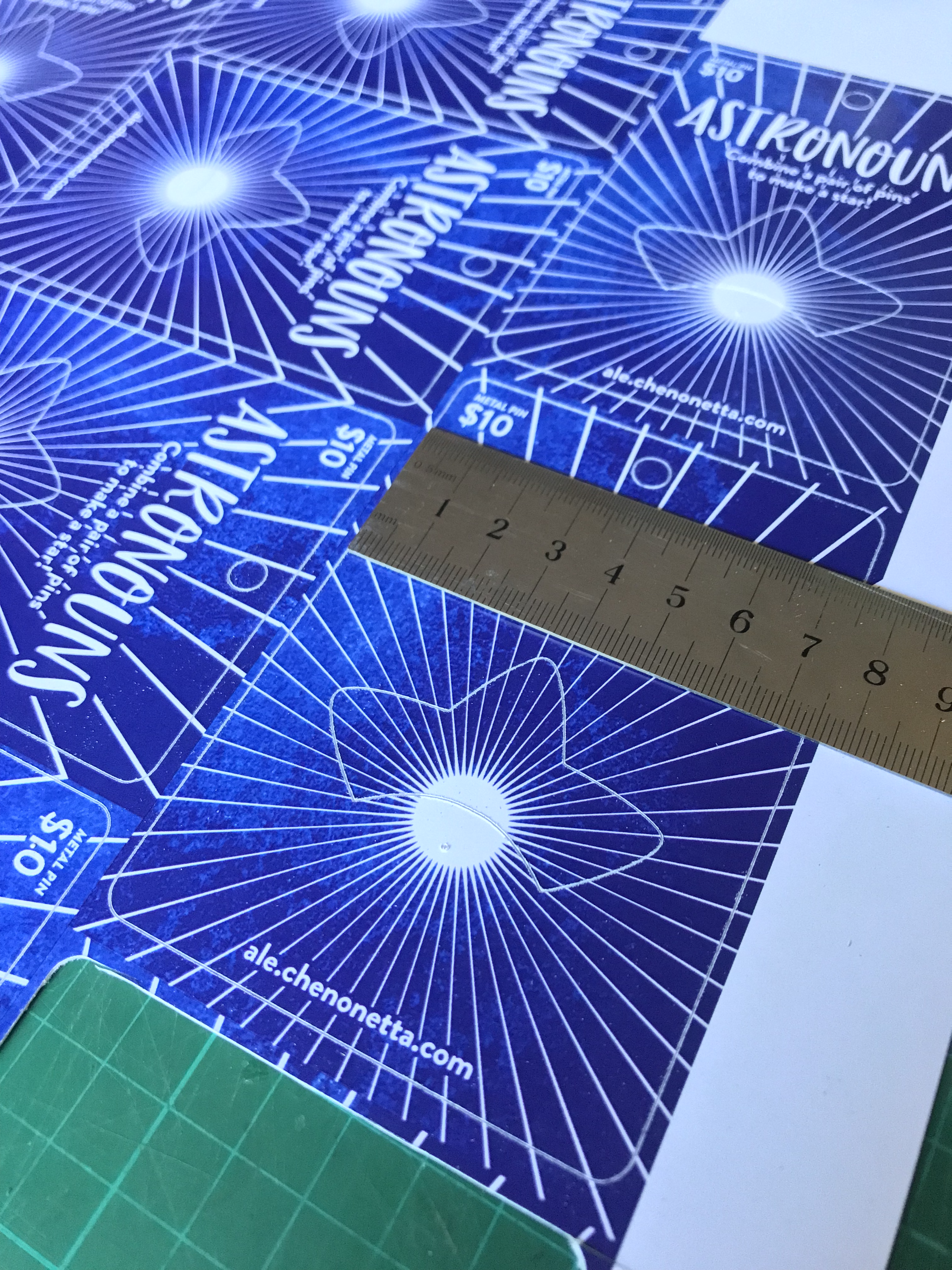
This time we’re going to use a template with registration marks to tell the Cricut where to perform cuts on a separately printed sheet of paper.

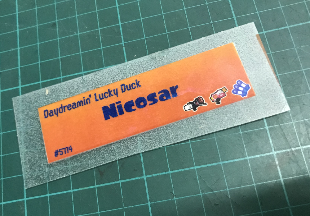
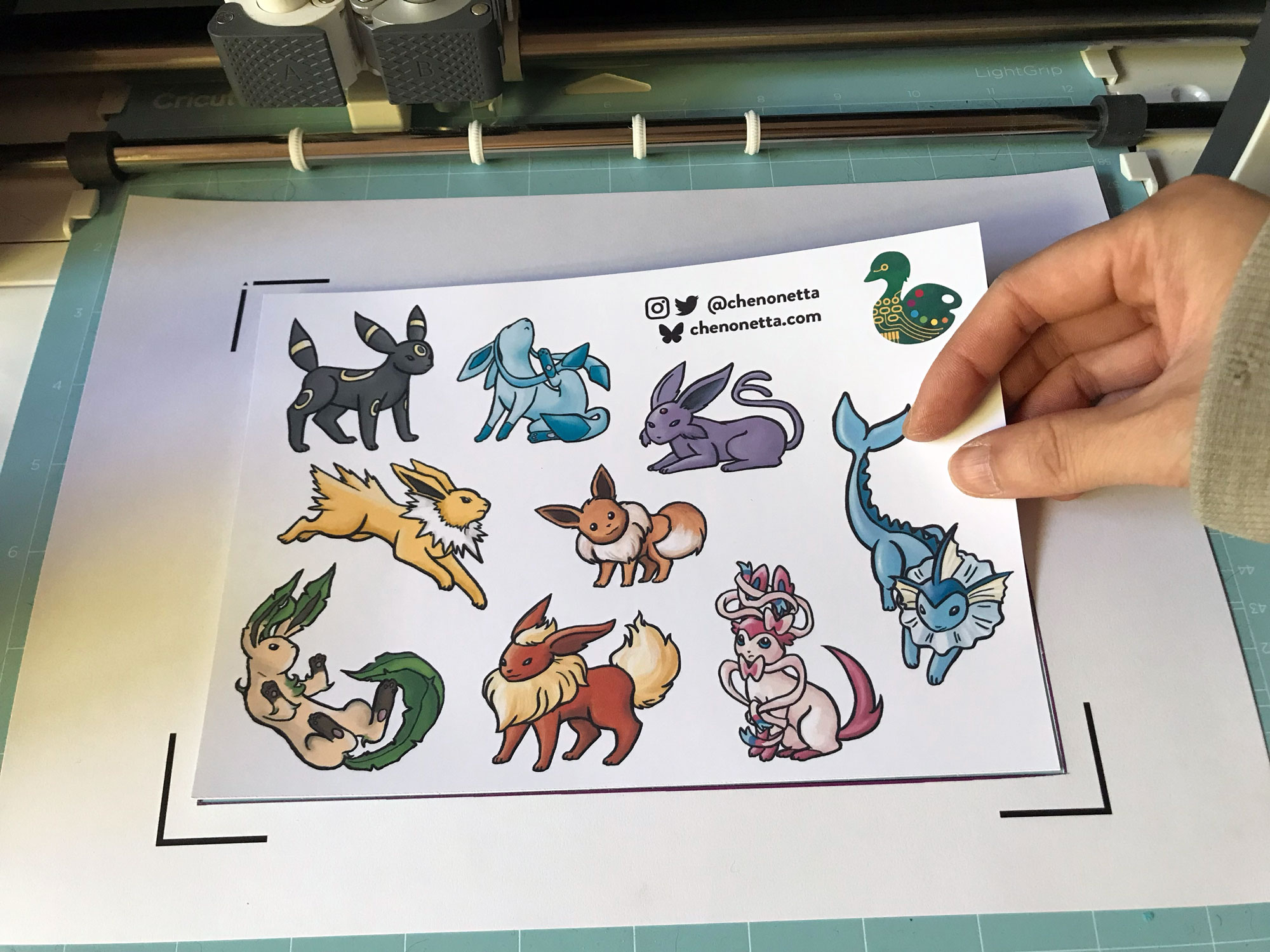
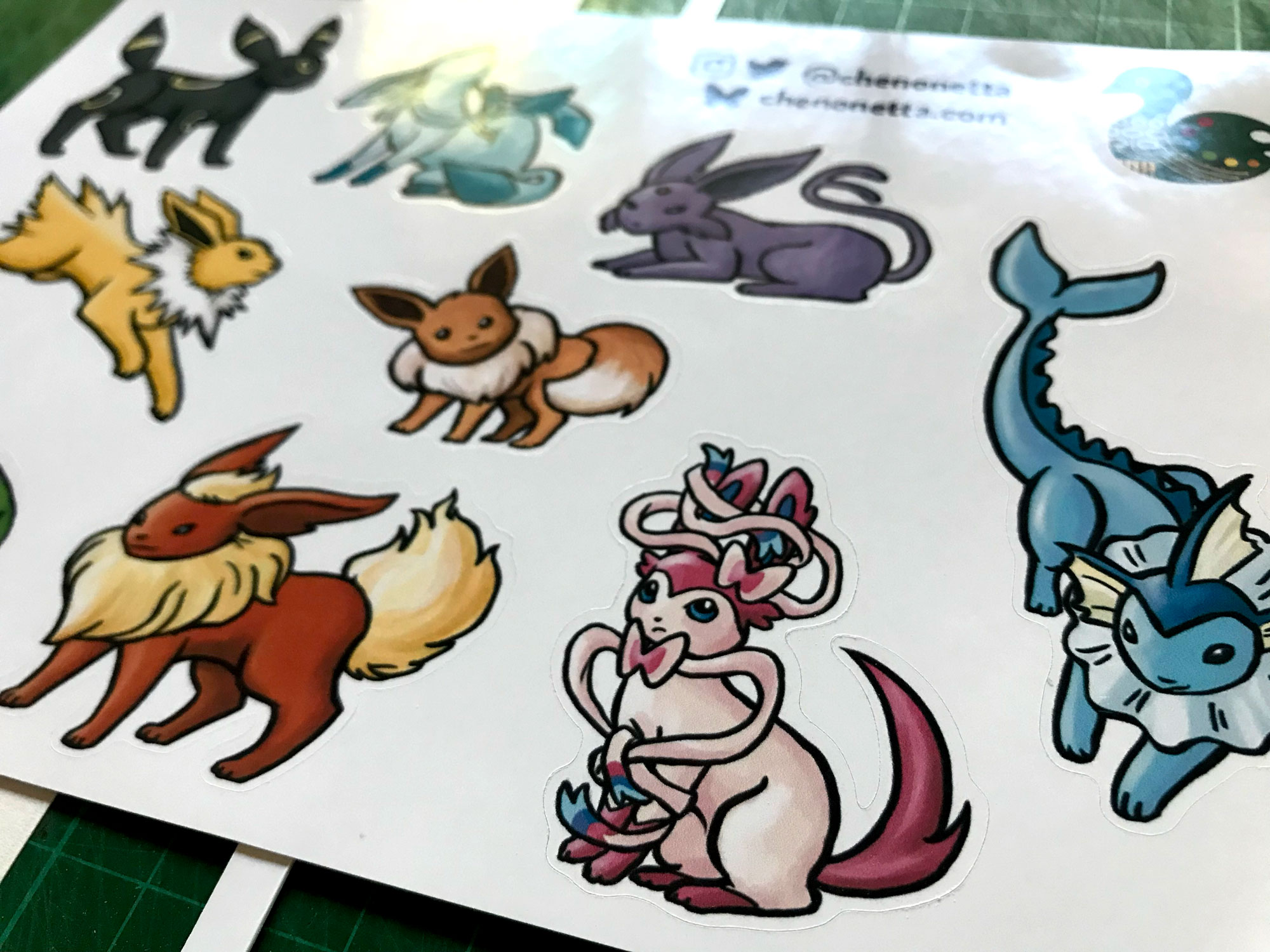
If you’re familiar with your Cricut, you probably see the below photo and have an immediate intuition about how to go about this hack! But I’ll share my method regardless.

Why?

Once again, we’re trying print larger than Cricut wants us to. This time, our reason for doing so is to avoid having to lose as much material to the registration marks as Cricut demands we sacrifice. It’s nearly 2cm around each edge, and if your printer already can’t print borderless-ly, you’re losing so much material!

Practically speaking, if you want to make A6 sticker sheets, you’d fit two on an A4 page, and if you wanted to make A5s you’d fit one, as shown in the diagram below.

Diagram showing the margins and measurements when using the Print and Cut feature for an A5 graphic

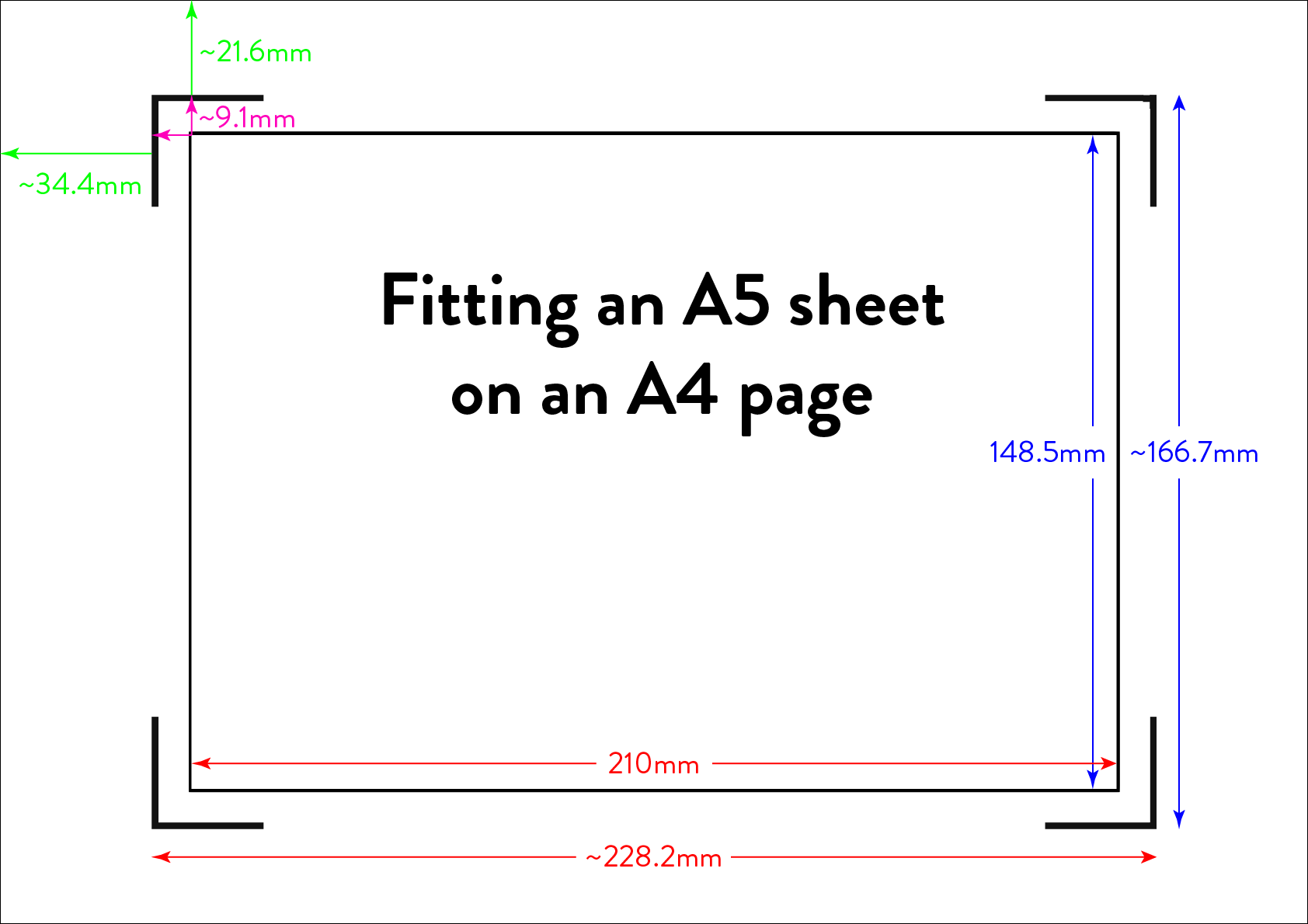
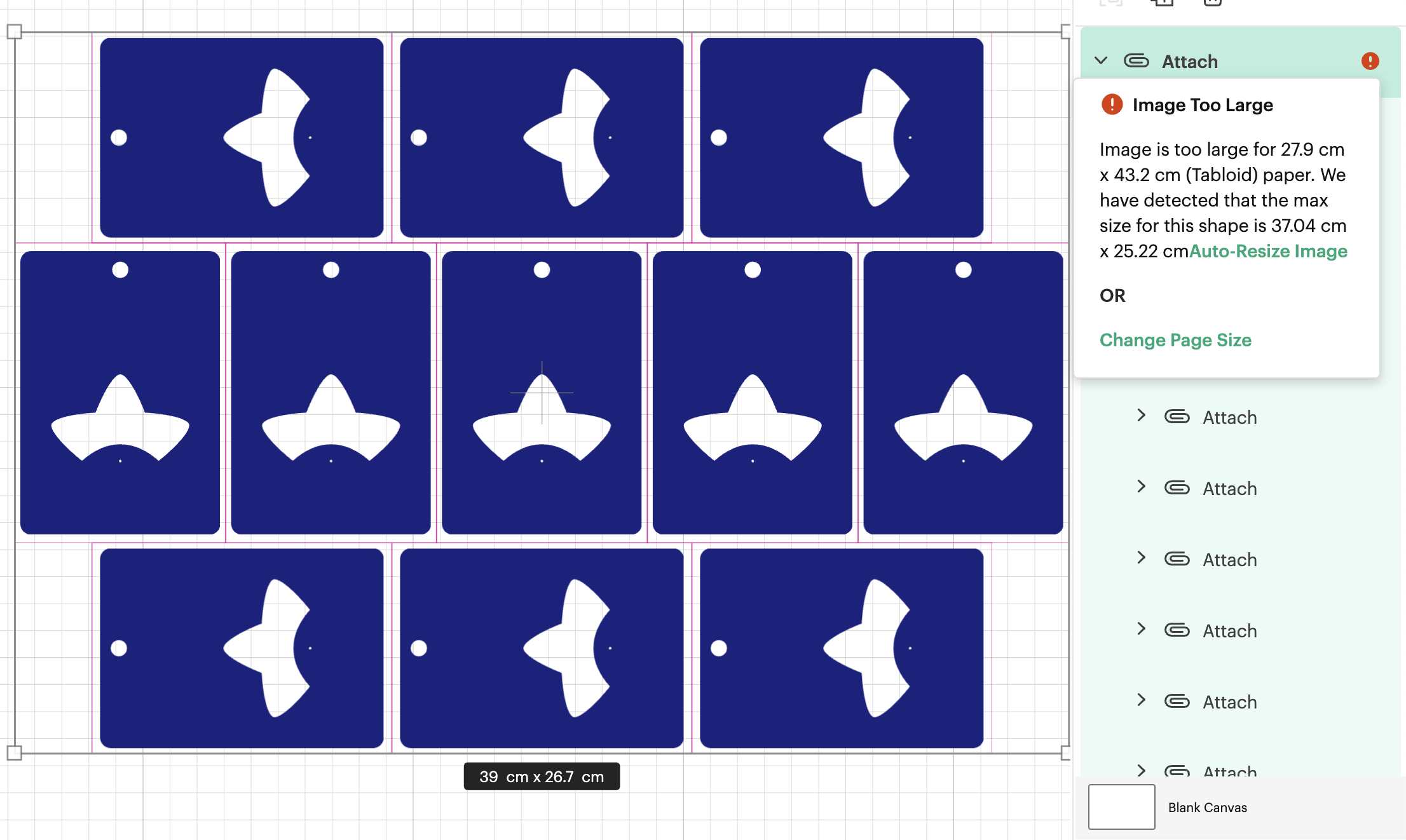
I’m willing to reduce my sticker sheet to 200⨉140mm, but Cricut still won’t let me fit two of those on a page. So let’s get hacking.

Drawbacks

Before we launch into the method, here’s some things to keep in mind:

  • You’re no longer going to get perfectly aligned cuts, as the manual alignment introduces room for error.
    • If your printer has a skew, this will become particularly noticeable as you might be rotating graphics in a way that exacerbates the skewing.
  • You’ll have more manual overhead for preparing your sheets.
    • I’m pretty fast at preparing my files now, but you still need to cut out each sheet to give to your cutting machine, which feels a little silly because the machine was meant to take that work away from us.
  • You need more software than just doing everything in Design Space.
    • I mention Adobe Suite software here, but others will be able to do most of this fine! I’m just indentured to Adobe. Don’t be like me, learn your hotkeys and workflows in the Affinity Suite and support perpetual licensing in software!

Method

Step 1: Prepare your sticker graphics

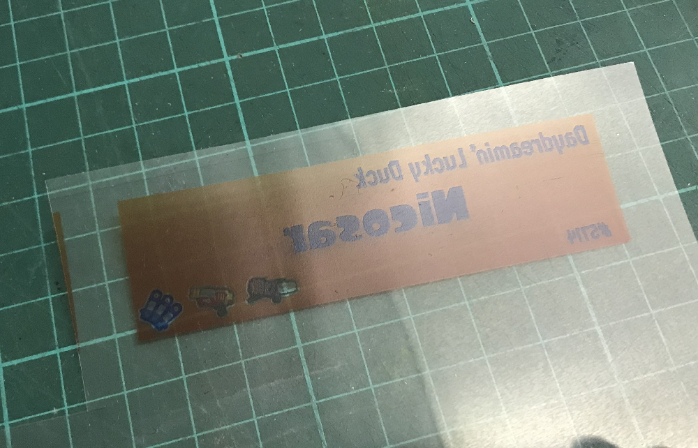
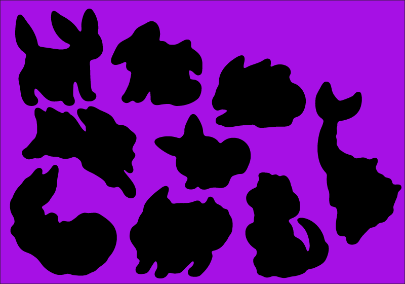
I prepare my images and vector cutlines outside of design space. This means I can have areas of the sticker sheet that aren’t cut out, like my logo and social media links.

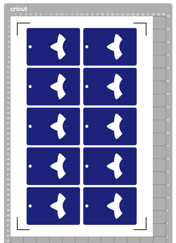
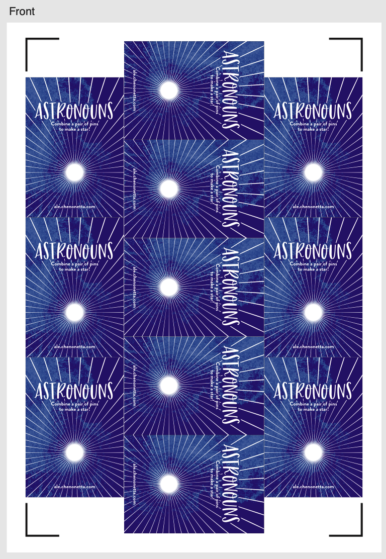
The first file you need is the one you’ll be printing. Repeat your design on your page as many times as you can fit, and then also place some marks for manual trimming. Here’s my example file (sorry about the watermarks). Notice the black lines in each corner of the page, and the lines in the middle of the page.

Print this file at 100% scale. Your printer might try to automatically scale your graphics to comply with your printer margins. Make sure that doesn’t happen!

Step 2: Prepare the cutlines

I generate the shape for each sticker by selecting the character in Photoshop, then use the Select => Modify => Expand menu item to add a border. I usually go with 20 pixels, which is a little more than 1.5mm at 300dpi.

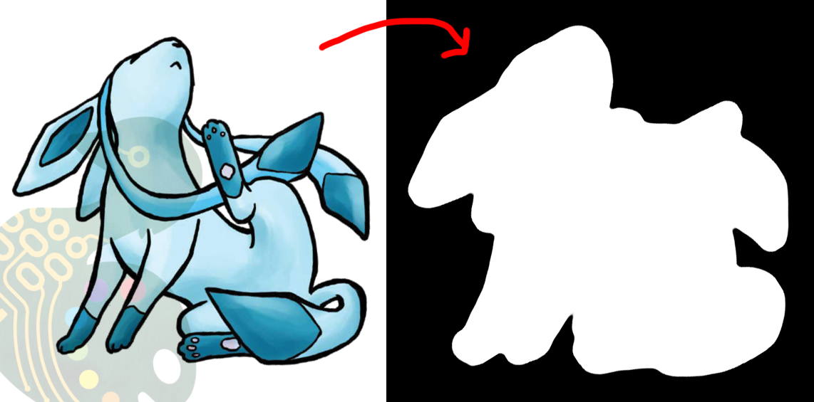
I then pull the black and white shapes into Illustrator and use the Image Trace tool to generate the vector outlines that will be used for cutting. I generally use the “Silhouette” preset, and then apply some smoothing to the lines (Object => Path => Smooth…).

Make sure to have the outline rectangle for your graphics as a separate image object as the rest of your graphics (you may need to “release compound path” or delete the outline and replace it with a rectangle, this will also get rid of any wibble that might have come from the image trace)

After these tweaks, I have a file ready to import into Design Space. Export it as an SVG (In my experience, the scale will be accurate if you use the Export menu item rather than the Save As, but other methods can cause scaling issues so just check the size once imported)

Step 3: The Template

Import your SVG into Design Space. Then, make sure all objects are grouped in an “Attach” group so that they’ll print and cut with your pre-prepared arrangement, and mark them all as Print and Cut.

Screenshot of Cricut Design Space showing silhouetted black blobs against a purple background

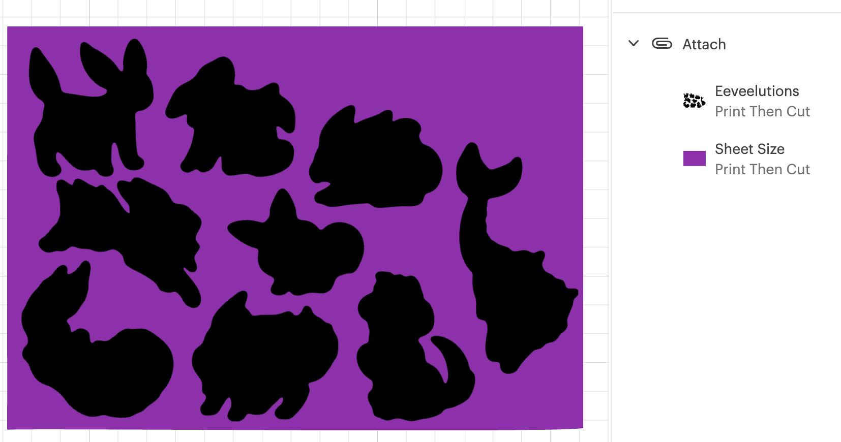
Click Make, but we’re not going to be sending this file to your Cricut yet.

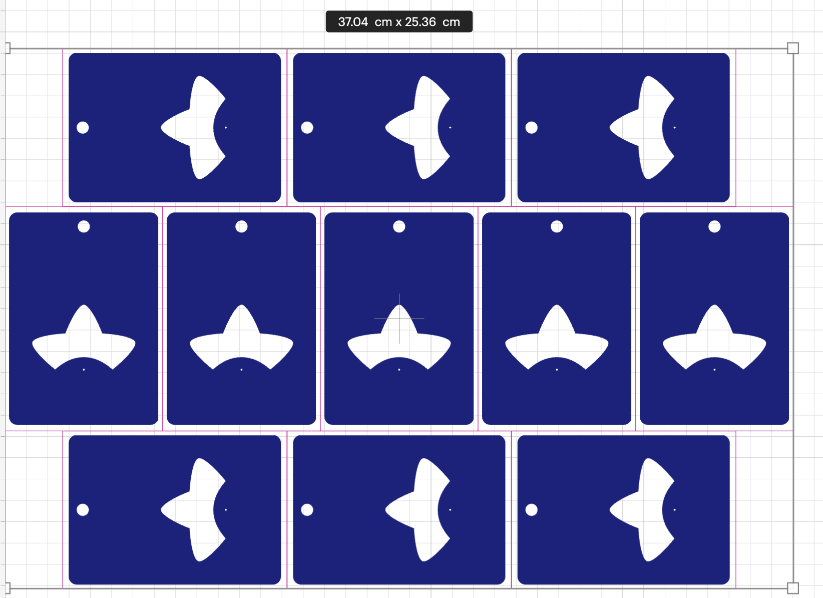
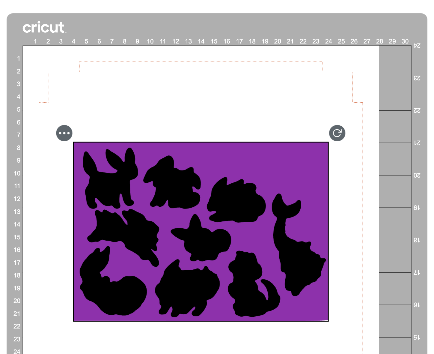
In the alignment page, move your graphic about 3 inches down the page, which will be enough clearance so that you can place and remove the sticker sheets into the templates without needing to unload the cutting mat.

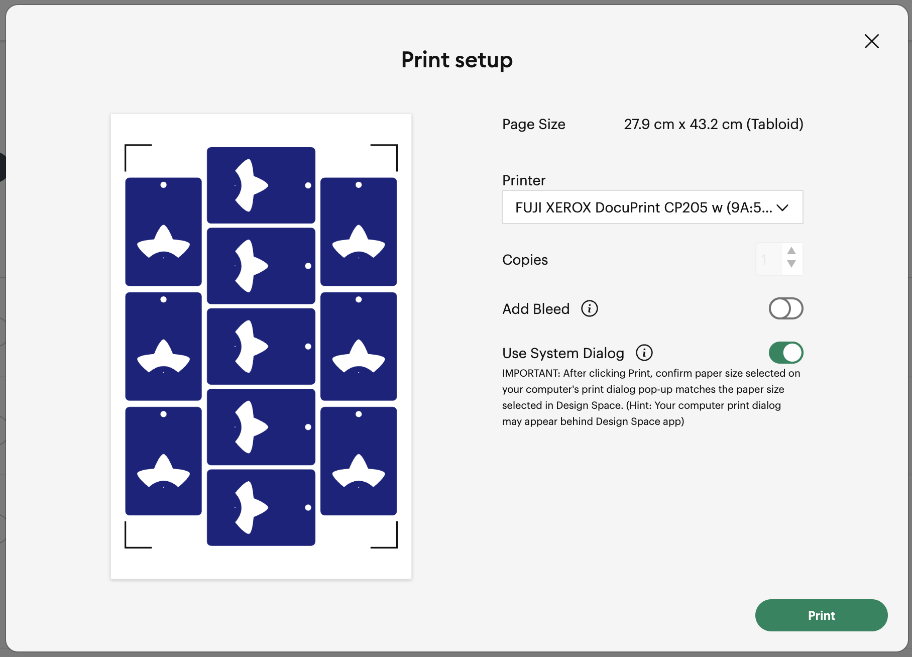
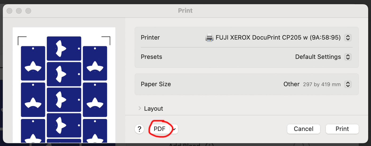
Then in the “Send to Printer” dialog, choose to “Add Bleed” and “Use System Dialog”. The system print dialog will pop up (or under, if you’re on macOS – drag the Cricut window away to find it) and you can print your file to a PDF.

Open your PDF in a graphics editor and make a white rectangle in the middle that matches your sheet size – in this case 200⨉140mm.

Print this file and use a craft knife and ruler to cut out the white rectangle. Try to be as accurate as you can!

PS, you could create the white void space and print the file directly from Design Space, but I like doing this because I can control a few extra things.

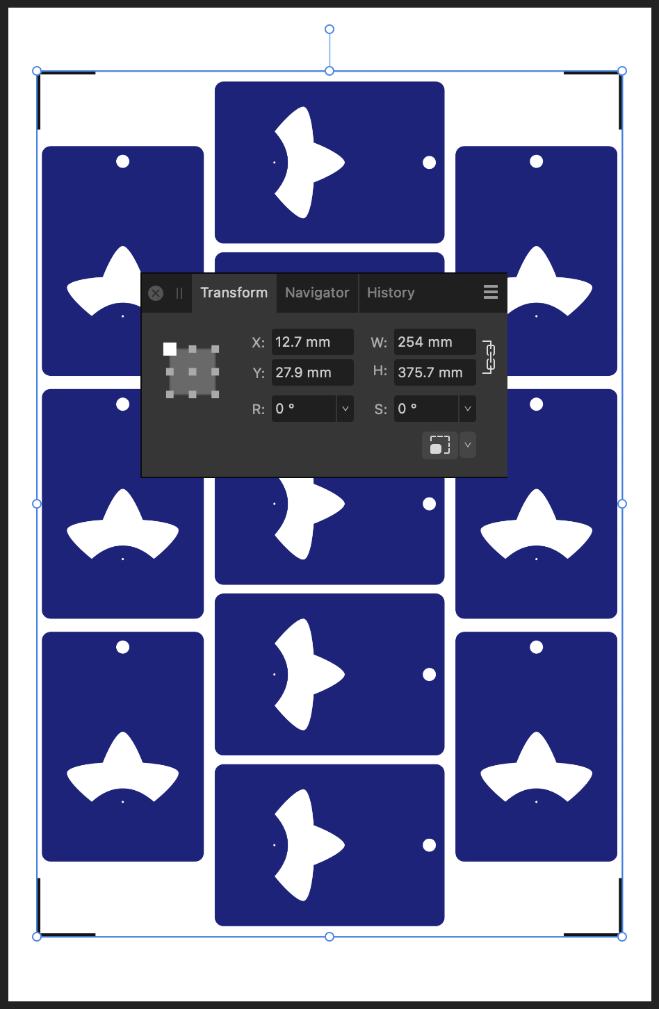
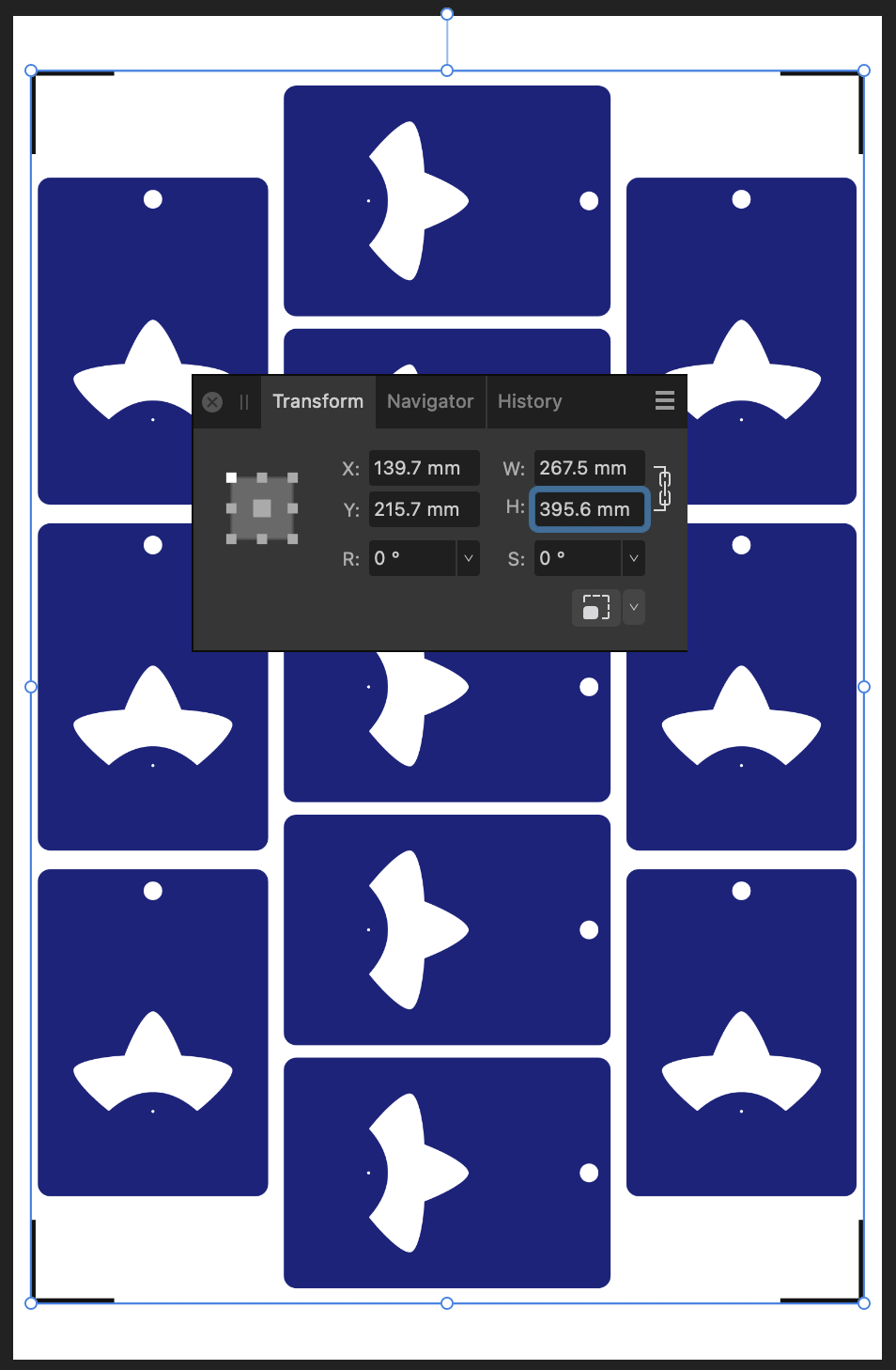
For example, Design Space won’t let me place my A5 graphic in landscape on an A4 page, but this way I can specify a larger paper size, then align the landscape image on the A4 page I’ll send to my printer.

Step 4: Cutting prep

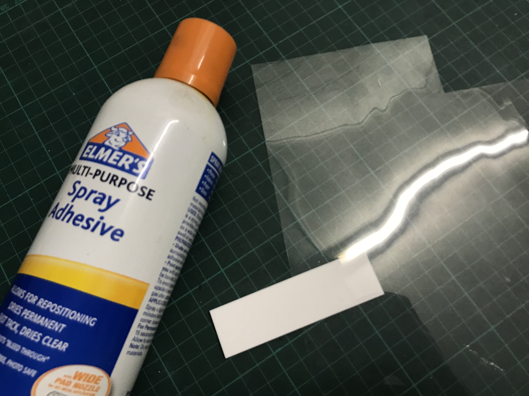
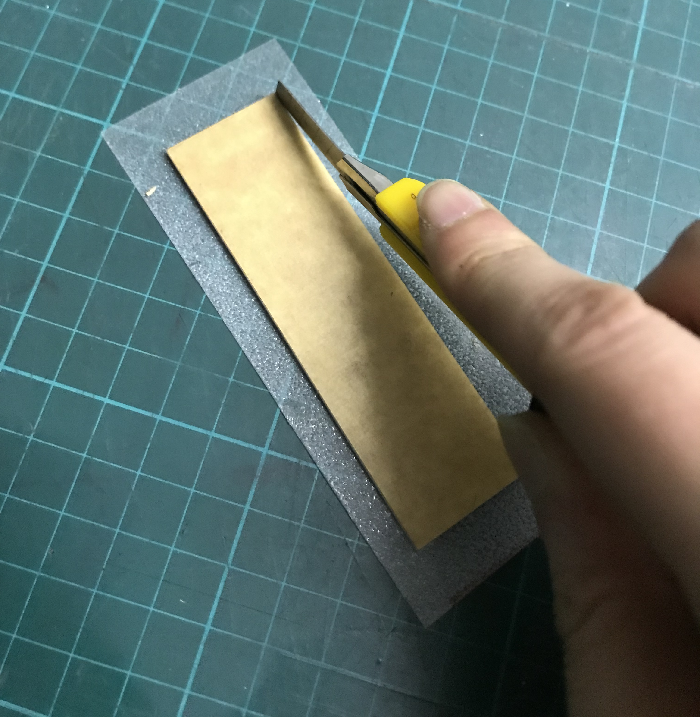
Take the sheets you printed in step 1 and use your craft knife and ruler to trim them to size. Again, I’ve chosen 200⨉140mm for my sheets.

Place your template file on your cutting mat, taking note of the position of the void space.

Place your trimmed sticker sheet in your template, aligning it with the void. Use the extra border around the void to help judge how square your sheet placement is.

It’s almost time to hit Make, but we need to do one tweak in Design Space.

We don’t need to cut the outline rectangle of our sheets, because we’re trimming them to size before aligning them into the template.

Removing the rectangle, or setting it to a “Guide” line type will cause the print and cut margins to change. Instead, I denote the rectangle as a Pen line. We won’t be loading a pen, and the machine will waste a little time on this, but we’ll also be able to tell whether it’s aligned correctly while it traces the outline in thin air.

Step 5: Make

Press that make button!

Drag your graphics so that they roughly align with where you’ve placed them on the cutting mat.

Then on the next page, say “I’ve already printed” and select your paper type. The Cricut will suggest you load a pen tool and the blade – don’t bother with the pen tool

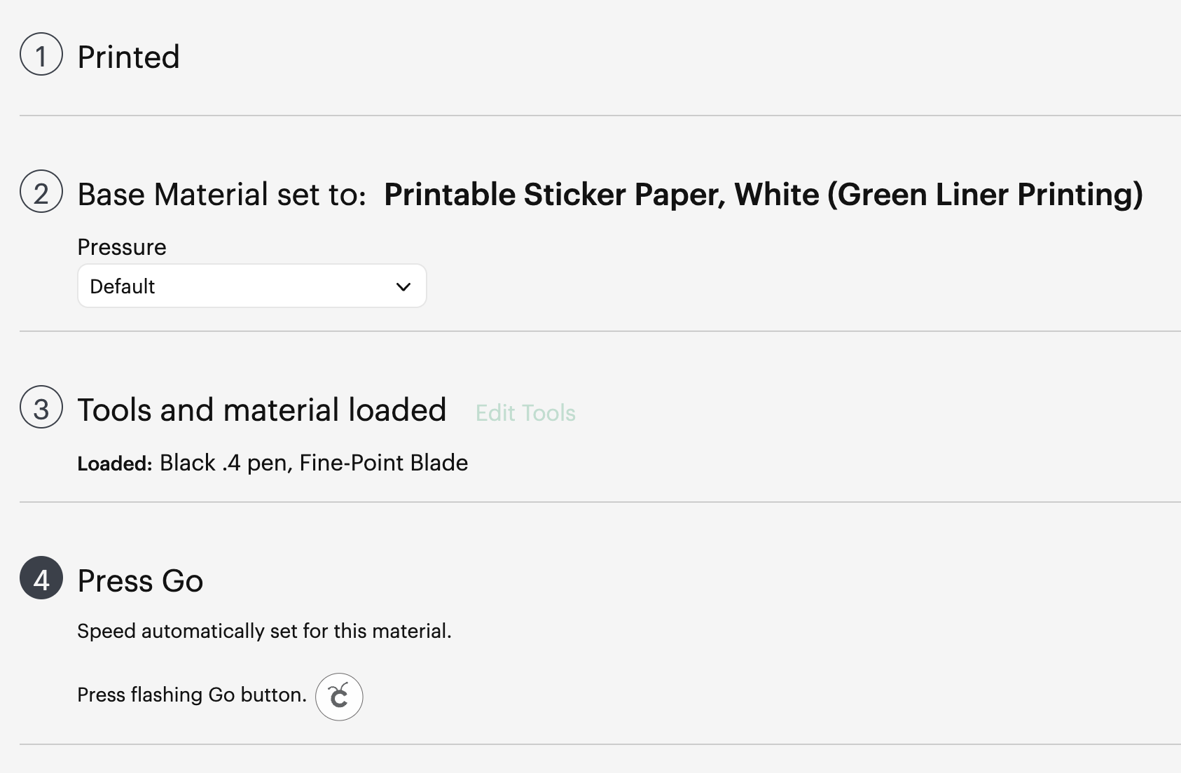
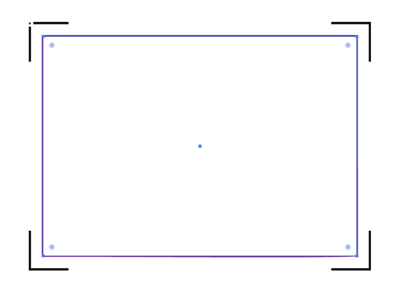
When you “Press Go”, the machine will start scanning for the registration marks.

It will then start drawing the outline of the sheet in thin air. While it does this, you can stare down the barrel of the empty toolholder to confirm that it’s aligned correctly with your page – if it appears to have misread the registration, you can cancel the job and try again. If it’s correct, your cutlines should also be correct.

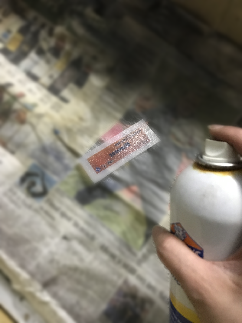
And when the job is done, and all your cutlines are correct, you don’t need to unload your mat. Remove your sticker sheet from the mat by curling it away from the paper. Now you can place your next sticker sheet into the void and press the Go button again and it will cut your next sheet without reading the calibration marks again. After adding a bunch of extra steps and work into this process, it’s nice to get a little timesave!

Closing Remarks

Once you make a template for a particular sheet size, you can reuse it for all your files that share the same size. Consider cutting your template from a thicker GSM paper to extend its lifetime and make it easier to affix without skewing.

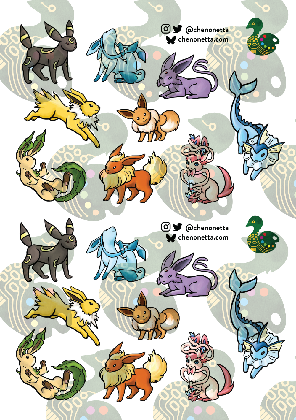
And finally, here’s the template with all its whitespace – that would have been wasted sticker paper if I cut this with the default workflow – next to the actual wasted material from my sheets. And a reminder, the sheet on the right fit two copies of the artwork vs the one on the left fitting only one!

Thanks for reading, if you found this useful please let me know!

Posted in: Behind the Art, Digital | Tagged: cricut, guide, hack, tutorial

Cricut “Print and Cut” Hack – print bigger

Posted on August 7, 2024 3 Comments

I’ve frequently felt constrained by the registration marks that the Cricut uses.

Screenshot of Cricut Design Space, showing a sample mat with registration marks

Understandably, they need to be bold and have a quiet region around them so that the cutter can determine where to line up its cuts.

Cricut also currently only provides 4 preset page sizes to print on, and again seems to assume rather generous print margins.

All these things added up mean that sometimes it’s not possible to place as many pieces on a page as you want. In the example above, I had to use a Tabloid paper size to convince Cricut to let me place the ten objects.

I reckon I should be able to fit even more of them in, and I should be able to do it on an A3 page. But Cricut says this layout is too large, despite the design itself being comfortably smaller than an A3 sheet.

(I’d actually love to fit even more than 11 onto an SRA3 page but making that layout work has so far eluded me, so let’s start with this hack first before trying anything more extreme.)

I discovered this hack by accident. I had taken my sheets to be printed at a print shop and they messed up the scaling. My pages came out about 3% smaller, but my Cricut didn’t complain. It happily executed the cutlines 3% smaller too. Evidently, there’s a generous margin of error for scaling.

So let’s use that to our advantage.

Step 1: Downsize the design in Cricut Design Space

Let’s humour Cricut by scaling the offending design to its recommended size.

(I suggest also keeping a copy of your original design to the side, in case you want to make changes at the original scale. To prevent the app from blocking you from proceeding to the “Make” step, hide the oversized objects.)

Step 2: Print to PDF

Click the “Make” button to proceed to the mat preview.

Do not move the designs on the mat – leaving things in their default position makes for the easiest alignment if you want to exit the Make step and return back to it again. Click “Continue”.

Open the “Print Setup” panel by using the “Send to Printer” button.

In this panel, select “Use System Dialog” to print your file to a PDF

On MacOS, the print dialog always appears behind the Design Space app, so drag the Design Space window out of the way when the “Preparing Print” spinner appears. Now save your file as a PDF instead of printing it.

Step 3: Scale up the PDF

It’s time to do some maths.

We originally had a design that was 39cm on its long edge, but we scaled that down to 37.04.

That means we now want to scale this file up again to be 39cm.

39 / 37.04 = 1.05291576674

This is a little more than 5% larger, which so far I have been able to make work. I don’t know what the upper limits of this technique are.

I’m editing the output file in Affinity Designer. The file that Cricut output has a long edge of 375.mm, so let’s type 375.7mm * 1.05291576674 into the H dimension field to get a new image of size 395.6 * 267.5mm.

While I’m here, I’m also going to set up my print graphics, allowing me to have better control of the bleed than using the normal Print & Cut workflow.

Step 4: Print

Print the file – I don’t have an A3 printer at home so I take my files to a print shop.

Step 5: Cut

Back in Cricut Design Space, choose your material. (You may need to select “I’ve already printed” so that the app lets you do so).

Affix your printed sheet to your cutting mat and load the mat. Press “Go” on your Cricut machine and let it do its cutting magic!

Another tip: If you’ve put graphics too close to the registration corners, you can temporarily place a sheet of white paper over them while the machine does its calibration. I usually just slide the white paper around by hand so I can remove it before the cutting begins. Coincidentally, the layout I’m demonstrating doesn’t use the edges so there’s plenty of “quiet” space to distinguish the registration marks from the artwork.

All done!

Here’s my cut pieces, at the scale that Cricut claimed I couldn’t have.

Actually, the vertical axis is a little bit off but this is good enough for my purposes and the bleed areas did their job. If I wanted to be a bit fussy about things, I would try moving around some of the cut lines, but do not move any cutlines that would change the outer bounds of the print, otherwise you’ll need to update your print file and recalculate its sizing too.

In summary:

Big Cricut wants to stop you from printing big. But follow these steps to break out from their boundaries!

  • Step 1: Downsize the design in Cricut Design Space
  • Step 2: Print to PDF
  • Step 3: Scale up the PDF (optionally, update any graphics)
  • Step 4: Print
  • Step 5: Cut

Please let me know if this guide was useful to you! Happy cutting!

Posted in: Behind the Art, WIP | Tagged: cricut, guide, hack, tutorial

Personalised Splashtag nametags

Posted on October 3, 2022 Leave a Comment

Follow these instructions to make your own splashtag that can be used as a name badge, fridge magnet… or whatever your heart desires!

You can also order a tag from me at this link: https://shop.chenonetta.com/product/personalised-splashtag/

Requirements:

  • Colour laser printer
  • Transparency paper/overhead projector film/acetate sheet
  • Spray adhesive
  • Plastic backing piece – I used 2mm thick acrylic, cut to the size that I wanted the badge to be.
  • Brooch finding

Prepare your splash tag

You can screenshot your splashtag from Splatnet, but the resolution might not be high enough for a nice print. If have issues with the resolution, you can use the resources at https://leanny.github.io/splat3/collectibles.html to recreate the splash tag. The font files for the Splatoon 1 and Splatoon 2 fonts are handy for replicating the text.

After composing the splashtag, mirror the design.

Print it onto the clear film, and cut it out leaving a generous margin (at least 10mm) around the edges.

This design has been printed at 87.5mm wide by 25mm tall.

Assembly

Apply glue to the the side of the sheet that you printed the text on.

Now align the transparency with the plastic backing and press them together. Make sure to only handle the extra margin of the plastic film so that you avoid smearing the glue on the splash tag itself.

Once you are confident that things are stuck well in place, you can trim the margin away from the transparent film. Tilt the blade slightly inwards – try to avoid leaving any overhanging plastic sheet, as this can catch and lead to the film peeling away from the plastic.

It’s done! You can now attach a finding to the back.

Posted in: Behind the Art, Crafts, Lasering | Tagged: splatoon, tutorial

How to make: Squid Lamp

Posted on April 27, 2022 Leave a Comment

PRERELEASE

You’ll notice that these instructions are very sparse on images. At this time I have only completed the text of the guide. Even though the images will be necessary to make sense of these instructions I am providing them now as an incentive for me to return to finish this guide at a later date.

This is a guide to making a USB powered squid lamp, similar to but not exactly like the one pictured below.

If you would like to commission a fully assembled lamp, please email me at ale@chenonetta.com. Current pricing is $150AUD per lamp before shipping.

Components

I have included some basic price guides including shipping fees, but you can likely source some parts for cheaper! Prices are in AUD. Some of the links are affiliate links – using these to order your parts helps support me!

Electronics

  • 5V LED Strip (100IP30) $16
    • Used to illuminate the squid colour. 1 metre will supply almost 4 lamps.
  • 5V LED Strip (30IP30) $7
    • Used to illuminate the eyes. 1 metre will supply almost 4 lamps.
    • You could cut individual LEDs from the 100IP30 strip and space them out instead of buying this separate strip type. Filling the entire eye space with a 100IP30 segment is overkill so I use this more sparse strip as a convenience.
  • ESP2866 controller $5
    • You can use an ESP32 instead If you need a Giteki certified device for use in Japan
  • USB Micro Cable $5

Plastic acrylic sheets

I use sheets with a glossy finish.

  • 2mm Black, approx 370x205mm $10
  • 3mm Frosted, approx 440x225mm $15

Other

  • 1mm white boxboard, 265x38mm
    • An A4 sheet will supply 5 lamps
  • Masking tape
  • Wire for joining LED strip lengths
  • Heatshrink to fit over the LED strips (approx 10-12mm diameter)
  • Glue that can bond plastic to plastic.
    • I usually use SciGrip Weld-On 3, a water-consistency solvent that bonds very quickly, and SciGrip Weld-On 16 which is more viscous. Super glues will probably work fine.

Equipment

You will need access to the following specialised equipment. If you don’t own these yourself look out for your local Makerspace or tool library!

  • Laser engraving machine
  • Oven and/or heat gun
    • You could use your home oven but I prefer to use a dedicated crafting oven.
  • Soldering Iron

Assembly Instructions

Step 1: Cut the acrylic

Peel the protective paper from the back sides of the black and frosted acrylic. Leave the paper on the side that faces upwards while in your laser cutter. The paper will provide protection for the parts while we work on assembly.

Frosted parts file: DXF / SVG (Dimensions: 434×219.9mm)

Black parts file: DXF / SVG (Dimensions: 367.58×201.26 mm)

In these files red lines should be cut, blue and green should be vector engraved (ie, cut but with less power).

Blue lines should be a kiss cut allowing for the front protective paper to be peeled off.
The green line should be a slightly deeper cut to assist bending of the tentacles.

Step 2: Glue the face plates

Peel the areas of the frosted pieces that correspond to black parts.

You should now be able to align the black pieces with the exposed frosted sections and glue them in place.

I apply the Weld-On 3 by dipping an old paintbrush into the glue. I then touch the wet paintbrush to where the two pieces of acrylic meet and the glue is drawn into place via capillary action. This creates a strong bond within a minute.

⚠️ Wear appropriate PPE when working with solvent glues. Nitrile gloves, safety goggles and a respirator are recommended.

Step 3: Bend the side walls

Preheat your oven to 160°C

Peel the protective paper off the rectangular pieces of frosted acrylic. If left on, these pieces would leave sticky residue on the parts as we bend them.

I recommend working on one piece at a time. Place each piece in the oven and let it sit for about 5 minutes. It should be floppy when you pull it out. If the piece forms bubbles it has sat in the oven for too long.

Form the pieces into shape using the black outline of the face plate as a guide. You’ll be using the long piece to form the top head of the squid, the two identical pieces to make the left and right tentacles and the shorter piece with the groove in the middle of it to form the middle tentacles.

If you cannot fit the full length of the piece into the oven at once you can first bend it by heating it with a heat gun or by placing the piece in the oven with the door open so that half of the sheet can be bent.

If you don’t have an oven that you feel comfortable placing your acrylic into you can heat your pieces using a heat gun. You’ll need to work slowly, bending in sections rather than forming the full shape in one go.

⚠️ Wear heat proof gloves when handling the hot acrylic!

It can be difficult to bend the sheets correctly. I have included some files for jigs that can be cut from 3mm MDF.

Jig file: DXF / SVG (Dimensions: 385.28×328.37mm)

To use the two-part jigs, rest the hot piece of acrylic against the bottom piece, then press the top piece into it to create the indentations.

The large jig is designed for the long piece of acrylic to be wrapped around it. Hold the ends in place so that they cool without expanding outwards again.

To speed up cooling of the piece, you can wave the pieces in the air so that cool air passes over them quickly, or blow cool air across them.

Step 4: Cut the socket hole

This guide assumes that you’ll wind the USB cable through a hole in the side of the lamp.

There are alternatives (my current lamp design provides a micro USB socket on the outside) but they’re complicated enough that I won’t go into them in this document.

Options:

  1. Drill/cut a large hole in the side big enough for the whole micro USB cable to fit through
  2. Cut an approx 5mm diameter hole then bisect the piece through the hole

The option you pick will depend on which aesthetic tradeoff you prefer. For 1, the large hole will cause the insides of the lamp to be seen from some angles. 2 will have a visible line across the wall where the piece was split into separate parts.

Step 5: Glue the sides

One of the face plates has a slot in its tentacle. Place it face down (with the black acrylic on the bottom, and the frosted on top).

Glue the walls of the lamp to the edges of this piece.

If you cut the side tentacle in half in the previous step, then remember to feed the USB cable through the hole before gluing the walls in place!

Step 6: Make the eye sheath

The eye sheath holds the two plates of the lamp together without any glue! It also holds the LED strips, allowing for beautiful illumination of the edges of the lamp.

Cut a length of 1mm boxboard to 38x265mm. I recommend cutting the long side against the grain – you want to be able to easily bend the long loop. This video explains how to find the grain of your sheet.

Mark two parallel lines 14mm away from the long edge. This marks a 10mm gap in the middle to align your LED strips to. Flip over the piece and mark lines on the opposite side, too.

Line both long edges of the piece with masking tape. The tape protects the edge of the cardboard and provides friction when inserted into the squid’s face plates.

Bend the cardboard in half, then slowly curl the cardboard in the opposite direction of this bend. You are aiming to make the shape of the eye mask of the squid.

It can help to slot the piece into one of the face plates as you work. There should be about a 3mm gap between the ends of the cardboard.

Join the loop with a piece of masking tape on the top and bottom, leaving a gap to allow the LED strip to pass through.

Step 7: Make the LED strip

When working with addressable LEDs, take note of the arrows denoting the direction of the data line.

Start of strip ➡️➡️➡️➡️ End of strip

Cut a length of 100IP30 strip to 26 LEDs long (26cm) – this piece will be called Segment A from now on

Cut a length of 30IP30 strip to 8 LEDs long (approx 26.6cm) – this piece will be called Segment B

Cut a piece of heatshrink, 1-2cm long

Slide the heatshrink over the start of Segment B, and push it clear of the solder pads. Align Segment A and Segment B, making sure to double check the direction of the data line and that the correct terminals are in contact.

  • The 5V, data and G pads of each segment should meet their corresponding pads on the other segment.
  • The arrows should face in the same direction, with Segment A leading INTO Segment B.

Once you’re happy with the configuration, solder the two strips together. This video provides a good guide on soldering joins between LED strips. If your strip has exposed pads on the bottom side as well you can follow the instructions from further along in the same video to reinforce your join from both sides.

After joining the strips, pull the heatshrink over the join and shrink it there, providing protection for the connection you just made.

Solder power, data and ground wires to the start of Segment A. These should be about 7cm long.

Once happy with your wire joins, you can shrink a 1cm piece of heatshrink over them for protection.

Step 8: Attach the LED strip to the eye sheath

Crease Segment A after the 13th LED by facing the LEDs towards another and pinching the cut line.

Peel the backing off of Segment A and nestle the crease that you just made in the halfway fold of the eye sheath, lining up the strip with the guide lines you drew on earlier. Now stick down the sides of this segment, taking care to stay between the lines as you wrap the strip around the cardboard.

Feed the end of Segment B into the gap in the eye sheath and bend the heatshrink-covered area back over itself. You can now remove the adhesive from the back of Segment B and affix the strip to the inner face of the eye sheath.

Step 9: Prepare the controller

Connect the Wemos D1 mini into your computer using a micro USB cable. Install WLED to the controller at http://install.wled.me/

Desolder the LED on the board – otherwise the blue light may interfere with the appearance of your coloured LEDs.

Desolder the Reset button (optional – depending on how you orient the controller it may be more likely to bump the reset button accidentally).

Solder your wires from the LED strip to the adjacent 5V, G and D4 terminals. Take care to connect the correct leads to the right terminals! The LED strip has the 5V and G lines on opposite sides, while the Wemos has 5V and G next to one another.

If everything has been done correctly – plugging the D1 into power will light up 30 of the LEDs on the strip in an orange colour.

Step 10: WLED settings

Connect to the WLED Access point. Default SSID WLED-AP, password wled1234

At http://4.3.2.1/settings/leds set the LED count to 34.

In the “Segments” part of the WLED UI set up the first segment from LED 0 to 26 as the Squid Colour, and a second segment from 26 to 34 as the eyes.

You can upload my presets at http://4.3.2.1/settings/sec which will configure a number of default colour patterns.

Preset file: JSON

If you have a favourite preset, you can specify it as the startup pattern on the http://4.3.2.1/settings/leds page.

If you’ve connected WLED to your home network, replace the 4.3.2.1 with the IP of the lamp. You can find the IP address by checking the list of devices on your router, or by installing the iOS or Android WLED apps and searching for devices.

Step 11: Enclose the lamp

Slide the Wemos controller into the slot in the frosted acrylic. This slot provides a snug home for it to stay in the lamp and hides a lot of the shadow that would be cast by the controller.

Check that the cardboard eye sheath is smoothly bent and slot it into the body of the squid (the face plate that you’ve attached the walls to).

The other face plate can now be fitted over the eye sheath. You may need to jiggle it somewhat for it to fit snugly. Be patient and feel for how the cardboard fits into its slot. Once it’s in place the black border of the face plate will be flush with the walls.

Optional: Before attaching the face plate, line the walls of the squid with double-sided sticky tape. This provides some additional adhesion to hold your lamp together while still providing the option to reopen the lamp in the future if you need to do maintenance.

Now that lamp is fully assembled you can remove all of the protective paper! It’s done!

Closing Notes

There are a few differences between the lamp in this guide and the lamps I am currently making. Incorporating the below changes are left as an exercise for the reader

  • The power port. My v4 lamp includes a micro USB socket on the side, instead of threading the cable through the side of the lamp. I also take the 5V power from this socket instead of from the 5V pin on the Wemos D1 Mini, allowing me to set a higher current limit in the WLED settings.
  • This guide advises permanent solder connections instead of temporary connectors. I’ve used connectors like the JST XH2.54 (Dupont connectors would also work) to allow me to swap various parts in and out – this can be good for making and testing many lamps at once or for replacing a single module of the lamp if it is damaged.

License

These instructions are licensed under a Creative Commons Attribution-NonCommercial-ShareAlike 4.0 International License.

Also if you make a lamp for yourself PLEASE send me photos! Comment on this post, tag me on Twitter @alecatmew or email me!

Posted in: Behind the Art, Electronics, Lasering | Tagged: leds, splatoon, squid lamp, tutorial

Step-by-step: Faux floorboards using photoshop filters

Posted on August 1, 2019 Leave a Comment

I had a bit of fun yesterday trying to create a floorboard texture – I wasn’t feeling like drawing because my hands were a bit sore so I set myself the goal of doing things with just photoshop filters! Here’s a guide of how I achieved the look using just the Add Noise and Motion Blur filters.

Here are the ones I made yesterday. Below I try recreating the method and providing a walkthrough. I think today’s recreation is a little less successful (I started too dark) but the concepts applied can be experimented with endlessly to create a variety of different fun textures!

Image

Step 1: Fill the canvas with brown

Step 2: Add noise – Leaving Monochromatic unticked at this point will provide a bit of colour variety. A low Amount % will still allow the brown to be the dominant colour.

Step 2.5 (optional): Select the whole area and enlarge it – this one has been scaled to about 400% of its original size. In this step the interpolation mode doesn’t matter as much, in later steps we want to use Nearest Neighbour interpolation to do enlargements.

Step 3: Motion Blur. The distance of the blur will affect the grain of the “wood” 🙂

Step 4: Starting on the planks. Fill a new layer with brown again and then enter the add noise menu. This time I create select the monochromatic option

Step 5: Making blocky shapes.
Select a small area of the pixels and then enlarge them to 200% of their original size, making sure to use Nearest Neighbour interpolation.

Step 6: Offsetting blocks
Select every second row and displace them horizontally by one pixel.

Step 7: Enlarge the planks.
Using nearest neighbour interpolation again, enlarge the planks. You want them to be wider than they are tall.

Step 8: Take a copy of this layer, then apply a motion blur to it.

Step 9: Change the blend type on the layers. I recommend experimenting with overlay and multiply! I started this example using very dark colours so I now need to adjust them!

Step 10: Colour adjustments done. For this example I’ve just set the bottom layer to 50% opacity, the middle one to an Overlay blend with 20% opacity and the top layer to Overlay with 60% opacity. I’ve also stretched the middle planks layer so that the floorboards are much longer.

At this point you’re basically done. The edges of your generated floorboards will need to be trimmed, so make sure to plan for that.

You can adjust a few things to tweak the overall look of the floorboards – the lengths of the motion blurs, scaling the noise before the first motion blur, whether or not you add noise with the Monochromatic option ticked, and the pixel offsetting (try offsetting the overlay layers from one another so they don’t have the same highlights and shadows, or even use two completely different noise maps for each overlay layer!)

It’s worth also adjusting the colour balance of the two overlay layers too – the floorboards usually look better if there aren’t some really highlighted or dark ones sticking out.

And of course you can still do some manual adjustments to add more detail to your floorboards – maybe add shadows between them or add irregularities and whorls to the woodgrain.

Happy flooring!

Posted in: Digital | Tagged: blaugust, floorboards, photoshop, timber, tutorial, wood, woodgrain

Tutorial: How to create paint splatters in Adobe Illustrator

Posted on August 5, 2016 Leave a Comment

howtosplat

Past-me graciously supplied current-me with all of the partial steps of a tutorial. All I had to do was fill out the text. It’s not the most beautifully formatted tutorial, but I think it gets most of the main points across. Happy splatting!

Posted in: Digital | Tagged: blaugust, illustrator, splat, tutorial, vector

Recent Posts

  • Cricut Hacks #2 – Template frames
  • Rainbow Eagles
  • Cricut “Print and Cut” Hack – print bigger
  • Reflections on Tableturf
  • “Pearl’s Palette” custom keycaps

Archives

  • April 2025
  • November 2024
  • August 2024
  • March 2024
  • November 2023
  • August 2023
  • June 2023
  • April 2023
  • January 2023
  • December 2022
  • October 2022
  • August 2022
  • May 2022
  • April 2022
  • November 2021
  • September 2021
  • August 2021
  • August 2020
  • September 2019
  • August 2019
  • August 2018
  • May 2018
  • September 2016
  • August 2016
  • October 2015
  • September 2015
  • August 2015
  • April 2015
  • February 2015
  • October 2014
  • August 2014
  • July 2014
  • April 2014
  • March 2014
  • February 2014
  • September 2013
  • August 2013
  • July 2013
  • April 2013
  • March 2013
  • January 2013
  • December 2012
  • October 2012
  • September 2012
  • August 2012
  • July 2012
  • May 2012
  • March 2012
  • January 2012
  • December 2011
  • November 2011
  • September 2011
  • August 2011
  • June 2011
  • May 2011
  • March 2011
  • January 2011
  • December 2010
  • November 2010
  • October 2010
  • September 2010
  • August 2010
  • April 2010
  • March 2010

Blogroll

  • Hallucinfection
  • Jp's Lab
  • Leaflocker
  • Telling Stories

Copyright © 2025 Chenonetta Creations.

Theme by themehall.com.