Proairesis

Find Me On…

  • Facebook
  • tumblr
  • deviantArt
  • Storenvy
  • Home
  • About

leds

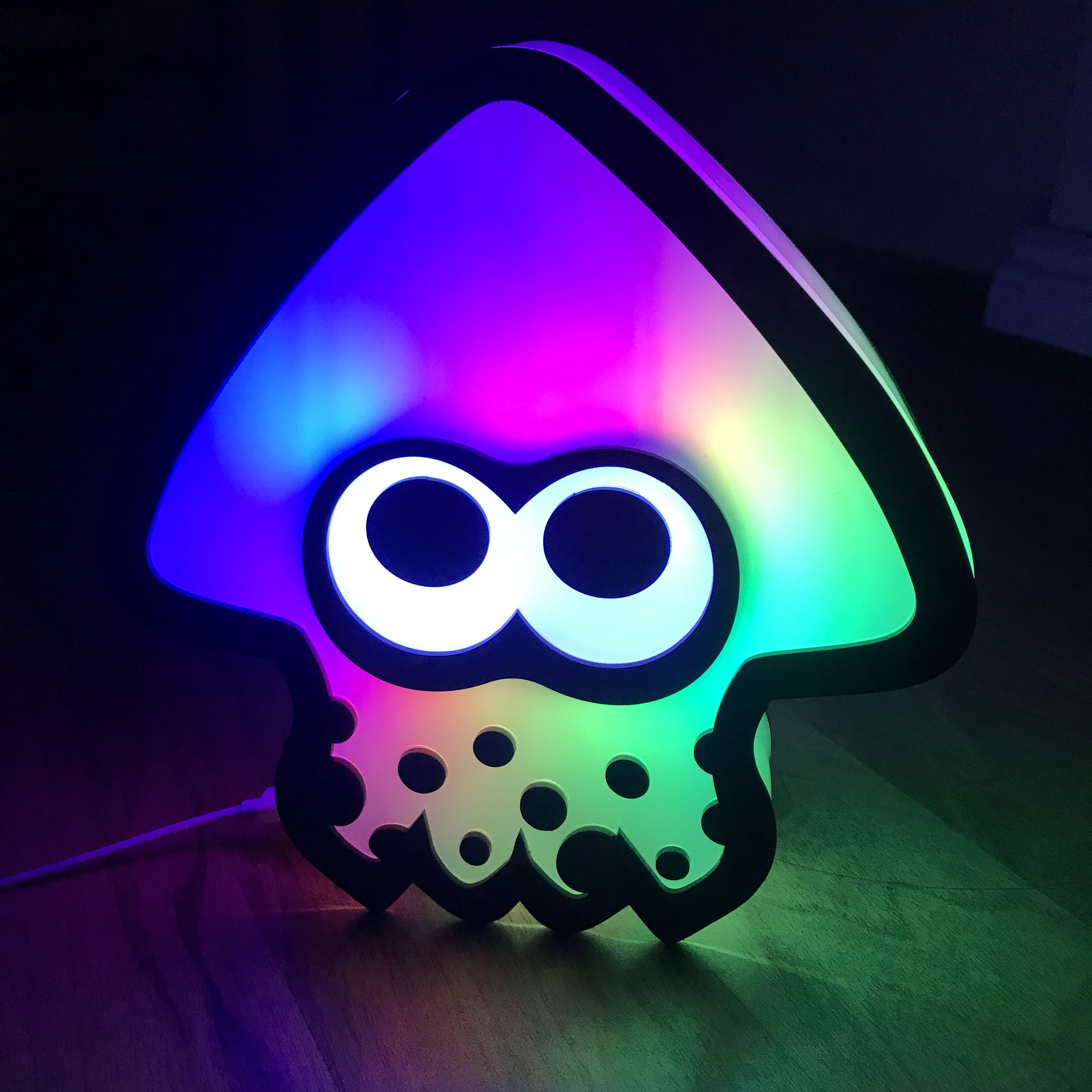
Put your Twitch Chat in control

Posted on May 8, 2022 Leave a Comment

Follow these steps to set up WLED colour changes as channel point rewards using Kruiz Control. These instructions are written specifically for my Squid Lamps but can be modified for use with any WLED project.

Example video of this setup in action:

Tonight’s project! pic.twitter.com/YcWZjQHnWd

— Alecat (@alecatmew) April 7, 2022

EDIT updated 2022-12-21

Check out Riekelt’s project, KrakenCommand for an alternative setup!

https://github.com/riek-lt/KrakenCommand

Original post follows

Download Kruiz Control

https://github.com/Kruiser8/Kruiz-Control/releases

Download and extract these files to somewhere you can remember.

Edit the Kruiz Control settings files

Inside the Kruiz Control directory is a “settings” folder containing a number of files that configure plugins against various services.

We need to modify settings/chat/oauth.txt and settings/twitch/user.txt.

OAuth Token

Generating an OAuth token allows us to talk with the Twitch API.

https://id.twitch.tv/oauth2/authorize?response_type=token&client_id=lavpr320qswa5w1whfcnpj6sb9lz7p&redirect_uri=https://twitchapps.com/tokengen/&scope=channel:manage:redemptions%20channel:read:redemptions%20chat:edit%20chat:read%20user:read:email

Click the above link to generate a token. You’ll be prompted to authorize permissions as a Twitch account.

Do not share this token with anyone else! It has permissions to manage your channel redemptions, to send messages in chat as the Twitch account that you choose and to see the email associated with the account. (I dunno why email address is needed but Comfy.js won’t work without that permission)

Open settings/chat/oauth.txt and replace the “token” part of the file with the generated token. Remove any spaces.

Channel Name

In settings/twitch/user.txt set the name of the channel that you want to watch for channel point redemptions. (Usually, your channel)

Chat User (Optional – not currently used)

Set settings/chat/user.txt to a Twitch channel. Setting this would allow Kruiz Control to send messages on your behalf to that channel.

Make the Custom Rewards in Twitch

https://dashboard.twitch.tv/viewer-rewards/channel-points/rewards

Make one reward per lamp colour.

Suggested list:

  • Rainbow Lamp
  • Blue Lamp
  • Cyan Lamp
  • Green Lamp
  • Yellow Lamp
  • Orange Lamp
  • Red Lamp
  • Magenta Lamp

Optional: icons in 112×112, 56×56 and 28×28 here: https://ale.chenonetta.com/stuff/ChannelPointIcons.zip 

Edit the Kruiz Control triggers.txt file

Replace the contents of triggers.txt with the following. Note that the OnChannelPoint triggers need to match the names of the rewards from the step above.

Replace the IP address on line 2 (http://192.168.0.113) with the IP of the lamp.

Your lamp needs to be connected to the same network as your streaming PC.

OnInit
API Url SquidBeakon "http://192.168.0.113/json/state"
API Method SquidBeakon POST
API Header SquidBeakon "Content-Type" "application/json"

OnChannelPoint "Rainbow Lamp"
API RawData SquidBeakon "{\"seg\": [{\"of\": 4, \"fx\": 110, \"sx\": 128, \"ix\": 128, \"pal\": 11}]}"
API Send SquidBeakon

OnChannelPoint "Blue Lamp"
API RawData SquidBeakon "{\"seg\": [{\"fx\": 0, \"col\": [[0, 0, 255]]}]}"
API Send SquidBeakon

OnChannelPoint "Cyan Lamp"
API RawData SquidBeakon "{\"seg\": [{\"fx\": 0, \"col\": [[0, 255, 200]]}]}"
API Send SquidBeakon

OnChannelPoint "Green Lamp"
API RawData SquidBeakon "{\"seg\": [{\"fx\": 0, \"col\": [[8, 255, 0]]}]}"
API Send SquidBeakon

OnChannelPoint "Yellow Lamp"
API RawData SquidBeakon "{\"seg\": [{\"fx\": 0, \"col\": [[255, 200, 0]]}]}"
API Send SquidBeakon

OnChannelPoint "Orange Lamp"
API RawData SquidBeakon "{\"seg\": [{\"fx\": 0, \"col\": [[255, 160, 0]]}]}"
API Send SquidBeakon

OnChannelPoint "Red Lamp"
API RawData SquidBeakon "{\"seg\": [{\"fx\": 0, \"col\": [[255, 0, 0]]}]}"
API Send SquidBeakon

OnChannelPoint "Magenta Lamp"
API RawData SquidBeakon "{\"seg\": [{\"fx\": 0, \"col\": [[255, 0, 255]]}]}"
API Send SquidBeakon

Future enhancements:

There is a feature request to enable accepting or rejecting of channel point requests. https://github.com/Kruiser8/Kruiz-Control/issues/39

Once this is implemented, we can update the trigger code to refund channel points if the lamp failed to update, and clear items out of the queue if it’s successful.

Alternatively, we could write our own code using Comfy.js!

Twitch currently only allows cooldowns on a per-reward basis. Kruiz Control has the ability to track its own cooldowns. See https://github.com/Kruiser8/Kruiz-Control/blob/master/js/Documentation.md#cooldown

Add Kruiz Control as a browser source in OBS

Add a new browser source. Select “Local File” and pick the index.html file from the Kruiz Control directory that you extracted in step 1. Keeping this browser source active will listen for Channel Point redemptions.

Select a reward in Twitch and if everything has been set up correctly, the lamp colours will change!

If you make any changes to the files inside the Kruiz Control directory, including the settings or triggers.txt files, you must refresh your browser source in OBS for the changes to take effect.

Appendix: A single reward with user-provided colour

If you don’t want to crowd your rewards with the lamp options, you can create one reward and allow it to control the lamp colours with the redemption message from your viewers.

Using a single reward also allows for the Twitch cooldowns to be used. This means that a viewer can’t override the colours set by another viewer until the cooldown ends.

Replace triggers.txt with the text from the code block below. Create a single reward named “Set Lamp Color” and turn on the “Require Viewer to Enter Text” checkbox.

This trigger will search the text of the message that was attached to the points redemption and if one of the color keywords is found then the lamp colour will change. It’s worth suggesting to the user what to enter in their message in the reward description, eg:

Set my squid lamp to rainbow, blue, cyan, green, yellow, orange, red or magenta by including one of these words in your message!

OnInit
API Url SquidBeakon "http://192.168.0.113/json/state"
API Method SquidBeakon POST
API Header SquidBeakon "Content-Type" "application/json"

OnChannelPoint "Set Lamp Color"
Param Lower message
Param Keyword message "rainbow"
If 3 {matched} == true
API RawData SquidBeakon "{\"seg\": [{\"of\": 4, \"fx\": 110, \"sx\": 128, \"ix\": 128, \"pal\": 11}]}"
API Send SquidBeakon
Exit
Param Keyword message "blue"
If 3 {matched} == true
API RawData SquidBeakon "{\"seg\": [{\"fx\": 0, \"col\": [[0, 0, 255]]}]}"
API Send SquidBeakon
Exit
Param Keyword message "cyan"
If 3 {matched} == true
API RawData SquidBeakon "{\"seg\": [{\"fx\": 0, \"col\": [[0, 255, 200]]}]}"
API Send SquidBeakon
Exit
Param Keyword message "green"
If 3 {matched} == true
API RawData SquidBeakon "{\"seg\": [{\"fx\": 0, \"col\": [[8, 255, 0]]}]}"
API Send SquidBeakon
Exit
Param Keyword message "yellow"
If 3 {matched} == true
API RawData SquidBeakon "{\"seg\": [{\"fx\": 0, \"col\": [[255, 200, 0]]}]}"
API Send SquidBeakon
Exit
Param Keyword message "orange"
If 3 {matched} == true
API RawData SquidBeakon "{\"seg\": [{\"fx\": 0, \"col\": [[255, 160, 0]]}]}"
API Send SquidBeakon
Exit
Param Keyword message "red"
If 3 {matched} == true
API RawData SquidBeakon "{\"seg\": [{\"fx\": 0, \"col\": [[255, 0, 0]]}]}"
API Send SquidBeakon
Exit
Param Keyword message "magenta"
If 3 {matched} == true
API RawData SquidBeakon "{\"seg\": [{\"fx\": 0, \"col\": [[255, 0, 255]]}]}"
API Send SquidBeakon
Exit

Appendix: Customising Eye colours

Add the following trigger commands to triggers.txt. Make sure to create the corresponding rewards in the Twitch dashboard!

OnChannelPoint "Red Eyes"
API RawData SquidBeakon "{\"seg\": [{},{\"col\": [[255, 0, 0]]}]}"
API Send SquidBeakon

OnChannelPoint "Lime Eyes"
API RawData SquidBeakon "{\"seg\": [{},{\"col\": [[255, 255, 0]]}]}"
API Send SquidBeakon

OnChannelPoint "White Eyes"
API RawData SquidBeakon "{\"seg\": [{},{\"col\": [[255, 255, 255]]}]}"
API Send SquidBeakon

Appendix: Multiple Lamps

This sample sets up SquidBeakon1 and SquidBeakon2 with their own URLs so that they can be driven by separate rewards. Full support for multiple channel point settings is left as an exercise for the reader.

OnInit
API Url SquidBeakon1 "http://192.168.0.113/json/state"
API Method SquidBeakon1 POST
API Header SquidBeakon1 "Content-Type" "application/json"
API Url SquidBeakon2 "http://192.168.0.114/json/state"
API Method SquidBeakon2 POST
API Header SquidBeakon2 "Content-Type" "application/json"
OnChannelPoint "Rainbow Lamp 1"
API RawData SquidBeakon1 "{\"seg\": [{\"of\": 4, \"fx\": 110, \"sx\": 128, \"ix\": 128, \"pal\": 11}]}"
API Send SquidBeakon1

OnChannelPoint "Rainbow Lamp 2"
API RawData SquidBeakon2 "{\"seg\": [{\"of\": 4, \"fx\": 110, \"sx\": 128, \"ix\": 128, \"pal\": 11}]}"
API Send SquidBeakon2

Appendix: Tips for displaying your lamps on stream

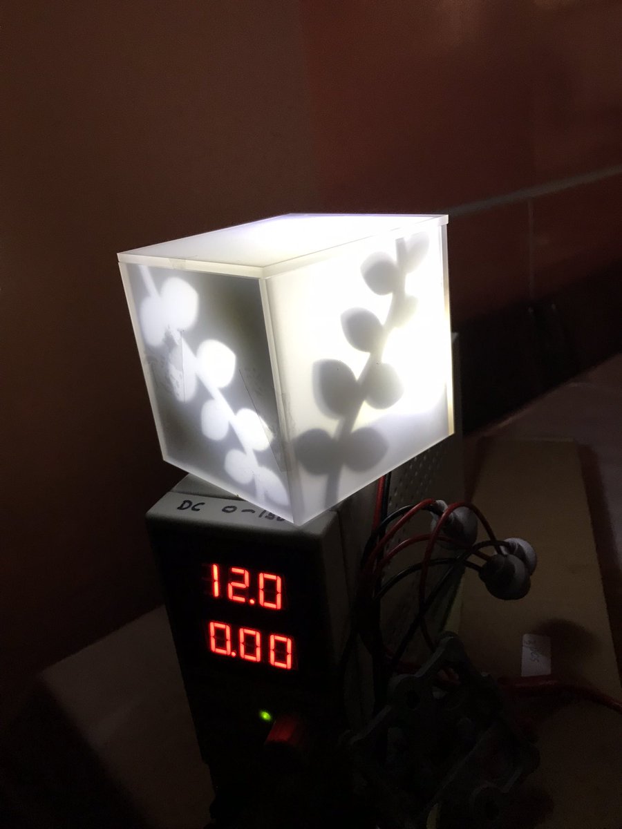
The lamps are emitting light, which can be difficult to capture on camera. Some tips to improve the appearance of the lights:
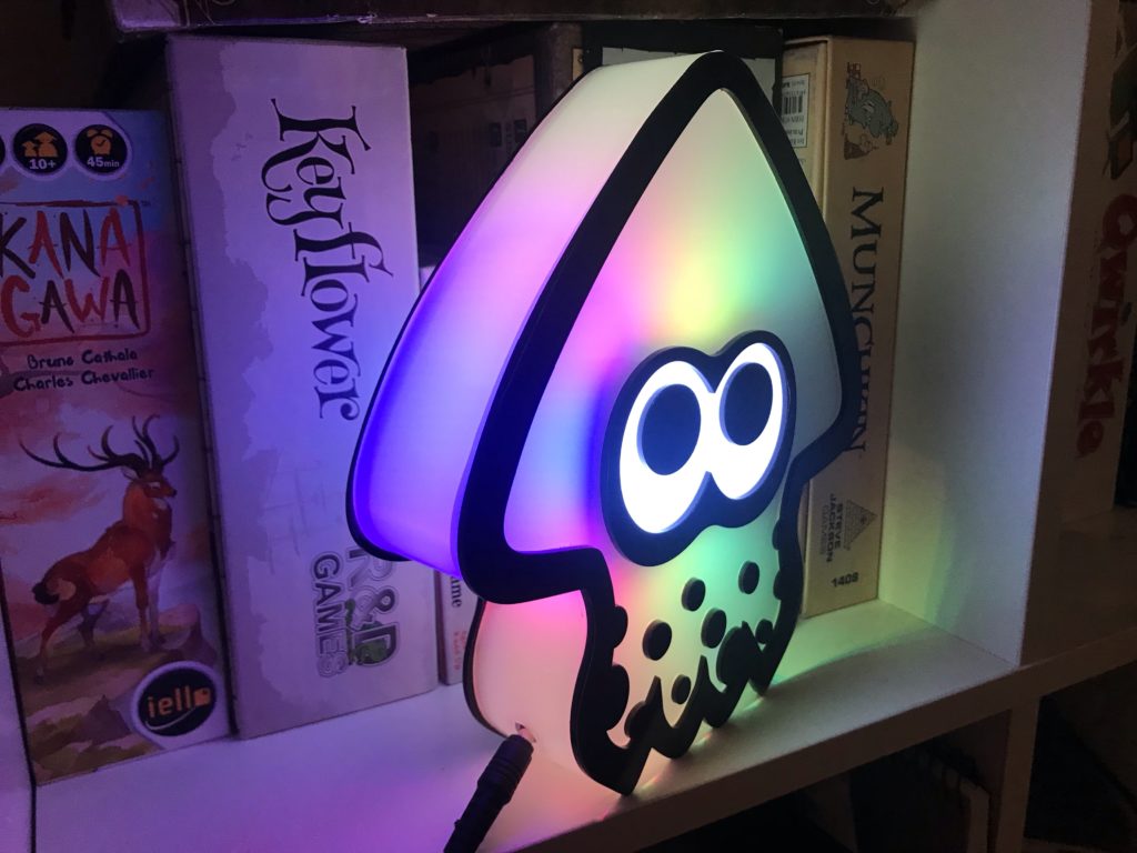
Reflected surfaces

Nearby white or other reflective surfaces will convey the colours of the light

Ambient lighting

The lights will be washed out by bright ambient lighting. The frequencies of sunlight can be especially effective at washing out the lamp colours. Indoor lighting or a dimmed room are best!
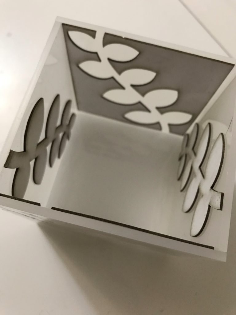
Diffusion

A piece of printer paper or baking paper in front of the lights can be used to diffuse the colours. This file contains templates for paper cutouts that can be placed in or on the lamp.

WLED JSON API

The commands in this document send JSON data via the WLED JSON API.

API documentation here:

https://kno.wled.ge/interfaces/json-api/

Posted in: Code, Streaming | Tagged: leds, squid lamp, twitch

How to make: Squid Lamp

Posted on April 27, 2022 Leave a Comment

PRERELEASE

You’ll notice that these instructions are very sparse on images. At this time I have only completed the text of the guide. Even though the images will be necessary to make sense of these instructions I am providing them now as an incentive for me to return to finish this guide at a later date.

This is a guide to making a USB powered squid lamp, similar to but not exactly like the one pictured below.

If you would like to commission a fully assembled lamp, please email me at ale@chenonetta.com. Current pricing is $90USD / $120AUD per lamp before shipping.

Components

I have included some basic price guides including shipping fees, but you can likely source some parts for cheaper! Prices are in AUD. Some of the links are affiliate links – using these to order your parts helps support me!

Electronics

  • 5V LED Strip (100IP30) $16
    • Used to illuminate the squid colour. 1 metre will supply almost 4 lamps.
  • 5V LED Strip (30IP30) $7
    • Used to illuminate the eyes. 1 metre will supply almost 4 lamps.
    • You could cut individual LEDs from the 100IP30 strip and space them out instead of buying this separate strip type. Filling the entire eye space with a 100IP30 segment is overkill so I use this more sparse strip as a convenience.
  • ESP2866 controller $5
    • You can use an ESP32 instead If you need a Giteki certified device for use in Japan
  • USB Micro Cable $5

Plastic acrylic sheets

I use sheets with a glossy finish.

  • 2mm Black, approx 370x205mm $10
  • 3mm Frosted, approx 440x225mm $15

Other

  • 1mm white boxboard, 265x38mm
    • An A4 sheet will supply 5 lamps
  • Masking tape
  • Wire for joining LED strip lengths
  • Heatshrink to fit over the LED strips (approx 10-12mm diameter)
  • Glue that can bond plastic to plastic.
    • I usually use SciGrip Weld-On 3, a water-consistency solvent that bonds very quickly, and SciGrip Weld-On 16 which is more viscous. Super glues will probably work fine.

Equipment

You will need access to the following specialised equipment. If you don’t own these yourself look out for your local Makerspace or tool library!

  • Laser engraving machine
  • Oven and/or heat gun
    • You could use your home oven but I prefer to use a dedicated crafting oven.
  • Soldering Iron

Assembly Instructions

Step 1: Cut the acrylic

Peel the protective paper from the back sides of the black and frosted acrylic. Leave the paper on the side that faces upwards while in your laser cutter. The paper will provide protection for the parts while we work on assembly.

Frosted parts file: DXF / SVG (Dimensions: 434×219.9mm)

Black parts file: DXF / SVG (Dimensions: 367.58×201.26 mm)

In these files red lines should be cut, blue and green should be vector engraved (ie, cut but with less power).

Blue lines should be a kiss cut allowing for the front protective paper to be peeled off.
The green line should be a slightly deeper cut to assist bending of the tentacles.

Step 2: Glue the face plates

Peel the areas of the frosted pieces that correspond to black parts.

You should now be able to align the black pieces with the exposed frosted sections and glue them in place.

I apply the Weld-On 3 by dipping an old paintbrush into the glue. I then touch the wet paintbrush to where the two pieces of acrylic meet and the glue is drawn into place via capillary action. This creates a strong bond within a minute.

⚠️ Wear appropriate PPE when working with solvent glues. Nitrile gloves, safety goggles and a respirator are recommended.

Step 3: Bend the side walls

Preheat your oven to 160°C

Peel the protective paper off the rectangular pieces of frosted acrylic. If left on, these pieces would leave sticky residue on the parts as we bend them.

I recommend working on one piece at a time. Place each piece in the oven and let it sit for about 5 minutes. It should be floppy when you pull it out. If the piece forms bubbles it has sat in the oven for too long.

Form the pieces into shape using the black outline of the face plate as a guide. You’ll be using the long piece to form the top head of the squid, the two identical pieces to make the left and right tentacles and the shorter piece with the groove in the middle of it to form the middle tentacles.

If you cannot fit the full length of the piece into the oven at once you can first bend it by heating it with a heat gun or by placing the piece in the oven with the door open so that half of the sheet can be bent.

If you don’t have an oven that you feel comfortable placing your acrylic into you can heat your pieces using a heat gun. You’ll need to work slowly, bending in sections rather than forming the full shape in one go.

⚠️ Wear heat proof gloves when handling the hot acrylic!

It can be difficult to bend the sheets correctly. I have included some files for jigs that can be cut from 3mm MDF.

Jig file: DXF / SVG (Dimensions: 385.28×328.37mm)

To use the two-part jigs, rest the hot piece of acrylic against the bottom piece, then press the top piece into it to create the indentations.

The large jig is designed for the long piece of acrylic to be wrapped around it. Hold the ends in place so that they cool without expanding outwards again.

To speed up cooling of the piece, you can wave the pieces in the air so that cool air passes over them quickly, or blow cool air across them.

Step 4: Cut the socket hole

This guide assumes that you’ll wind the USB cable through a hole in the side of the lamp.

There are alternatives (my current lamp design provides a micro USB socket on the outside) but they’re complicated enough that I won’t go into them in this document.

Options:

  1. Drill/cut a large hole in the side big enough for the whole micro USB cable to fit through
  2. Cut an approx 5mm diameter hole then bisect the piece through the hole

The option you pick will depend on which aesthetic tradeoff you prefer. For 1, the large hole will cause the insides of the lamp to be seen from some angles. 2 will have a visible line across the wall where the piece was split into separate parts.

Step 5: Glue the sides

One of the face plates has a slot in its tentacle. Place it face down (with the black acrylic on the bottom, and the frosted on top).

Glue the walls of the lamp to the edges of this piece.

If you cut the side tentacle in half in the previous step, then remember to feed the USB cable through the hole before gluing the walls in place!

Step 6: Make the eye sheath

The eye sheath holds the two plates of the lamp together without any glue! It also holds the LED strips, allowing for beautiful illumination of the edges of the lamp.

Cut a length of 1mm boxboard to 38x265mm. I recommend cutting the long side against the grain – you want to be able to easily bend the long loop. This video explains how to find the grain of your sheet.

Mark two parallel lines 14mm away from the long edge. This marks a 10mm gap in the middle to align your LED strips to. Flip over the piece and mark lines on the opposite side, too.

Line both long edges of the piece with masking tape. The tape protects the edge of the cardboard and provides friction when inserted into the squid’s face plates.

Bend the cardboard in half, then slowly curl the cardboard in the opposite direction of this bend. You are aiming to make the shape of the eye mask of the squid.

It can help to slot the piece into one of the face plates as you work. There should be about a 3mm gap between the ends of the cardboard.

Join the loop with a piece of masking tape on the top and bottom, leaving a gap to allow the LED strip to pass through.

Step 7: Make the LED strip

When working with addressable LEDs, take note of the arrows denoting the direction of the data line.

Start of strip ➡️➡️➡️➡️ End of strip

Cut a length of 100IP30 strip to 26 LEDs long (26cm) – this piece will be called Segment A from now on

Cut a length of 30IP30 strip to 8 LEDs long (approx 26.6cm) – this piece will be called Segment B

Cut a piece of heatshrink, 1-2cm long

Slide the heatshrink over the start of Segment B, and push it clear of the solder pads. Align Segment A and Segment B, making sure to double check the direction of the data line and that the correct terminals are in contact.

  • The 5V, data and G pads of each segment should meet their corresponding pads on the other segment.
  • The arrows should face in the same direction, with Segment A leading INTO Segment B.

Once you’re happy with the configuration, solder the two strips together. This video provides a good guide on soldering joins between LED strips. If your strip has exposed pads on the bottom side as well you can follow the instructions from further along in the same video to reinforce your join from both sides.

After joining the strips, pull the heatshrink over the join and shrink it there, providing protection for the connection you just made.

Solder power, data and ground wires to the start of Segment A. These should be about 7cm long.

Once happy with your wire joins, you can shrink a 1cm piece of heatshrink over them for protection.

Step 8: Attach the LED strip to the eye sheath

Crease Segment A after the 13th LED by facing the LEDs towards another and pinching the cut line.

Peel the backing off of Segment A and nestle the crease that you just made in the halfway fold of the eye sheath, lining up the strip with the guide lines you drew on earlier. Now stick down the sides of this segment, taking care to stay between the lines as you wrap the strip around the cardboard.

Feed the end of Segment B into the gap in the eye sheath and bend the heatshrink-covered area back over itself. You can now remove the adhesive from the back of Segment B and affix the strip to the inner face of the eye sheath.

Step 9: Prepare the controller

Connect the Wemos D1 mini into your computer using a micro USB cable. Install WLED to the controller at http://install.wled.me/

Desolder the LED on the board – otherwise the blue light may interfere with the appearance of your coloured LEDs.

Desolder the Reset button (optional – depending on how you orient the controller it may be more likely to bump the reset button accidentally).

Solder your wires from the LED strip to the adjacent 5V, G and D4 terminals. Take care to connect the correct leads to the right terminals! The LED strip has the 5V and G lines on opposite sides, while the Wemos has 5V and G next to one another.

If everything has been done correctly – plugging the D1 into power will light up 30 of the LEDs on the strip in an orange colour.

Step 10: WLED settings

Connect to the WLED Access point. Default SSID WLED-AP, password wled1234

At http://4.3.2.1/settings/leds set the LED count to 34.

In the “Segments” part of the WLED UI set up the first segment from LED 0 to 26 as the Squid Colour, and a second segment from 26 to 34 as the eyes.

You can upload my presets at http://4.3.2.1/settings/sec which will configure a number of default colour patterns.

Preset file: JSON

If you have a favourite preset, you can specify it as the startup pattern on the http://4.3.2.1/settings/leds page.

If you’ve connected WLED to your home network, replace the 4.3.2.1 with the IP of the lamp. You can find the IP address by checking the list of devices on your router, or by installing the iOS or Android WLED apps and searching for devices.

Step 11: Enclose the lamp

Slide the Wemos controller into the slot in the frosted acrylic. This slot provides a snug home for it to stay in the lamp and hides a lot of the shadow that would be cast by the controller.

Check that the cardboard eye sheath is smoothly bent and slot it into the body of the squid (the face plate that you’ve attached the walls to).

The other face plate can now be fitted over the eye sheath. You may need to jiggle it somewhat for it to fit snugly. Be patient and feel for how the cardboard fits into its slot. Once it’s in place the black border of the face plate will be flush with the walls.

Optional: Before attaching the face plate, line the walls of the squid with double-sided sticky tape. This provides some additional adhesion to hold your lamp together while still providing the option to reopen the lamp in the future if you need to do maintenance.

Now that lamp is fully assembled you can remove all of the protective paper! It’s done!

Closing Notes

There are a few differences between the lamp in this guide and the lamps I am currently making. Incorporating the below changes are left as an exercise for the reader

  • The power port. My v4 lamp includes a micro USB socket on the side, instead of threading the cable through the side of the lamp. I also take the 5V power from this socket instead of from the 5V pin on the Wemos D1 Mini, allowing me to set a higher current limit in the WLED settings.
  • This guide advises permanent solder connections instead of temporary connectors. I’ve used connectors like the JST XH2.54 (Dupont connectors would also work) to allow me to swap various parts in and out – this can be good for making and testing many lamps at once or for replacing a single module of the lamp if it is damaged.

License

These instructions are licensed under a Creative Commons Attribution-NonCommercial-ShareAlike 4.0 International License.

Also if you make a lamp for yourself PLEASE send me photos! Comment on this post, tag me on Twitter @alecatmew or email me!

Posted in: Behind the Art, Electronics, Lasering | Tagged: leds, splatoon, squid lamp, tutorial

Build Log: Splatoon RGB Lights – Part 1

Posted on November 30, 2021 Leave a Comment

It’s been a while since I’ve done a build blog so please indulge the wordiness here.

This is part 1 – covering the creative decisions (both planned and spontaneous) made when assembling this Splatoon-inspired lamp.

Originally tweeted by Alethea Lim (@alecatmew) on November 29, 2021.

Concept

I’ve had this idea bouncing in the back of my head for yeeeears – ever since I saw this line in the depths of Ikalog:

# IkaOutput_Hue: "Cameleon" Phillips Hue Lights.

Phillips Hue? Huh? Like… the smart lights? Does this code push colour updates to smart lights?

    def light_team_color(self, context):
        ...
        team1 = context['game']['team_color_bgr'][0]
        team2 = context['game']['team_color_bgr'][1]
        c1 = self.rgb2xy(team1[2], team1[1], team1[0])
        c2 = self.rgb2xy(team2[2], team2[1], team2[0])
        self.hue_bridge.lights(1, 'state', xy=c1, bri=255, sat=255)
        self.hue_bridge.lights(2, 'state', xy=c2, bri=255, sat=255)

Oh yes, yes it does.

At the time, I was running Splatoon LAN events and I thought to myself…

What if… I made squid-shaped lights to match the player icons that appear at the top of the screen during gameplay?

What if… I also combined it with the uptime tracking code in Ikalog to dynamically change the status of each light based on whether a player was active or splatted?

Then at a LAN, we could have a light stationed in front of each player to emphasise what was happening to them throughout the game!

Then I did nothing with the idea. Every few months I’d longingly watch DIY RGB panel videos on YouTube before getting stuck on deciding how ambitious to make the build and then moving onto something else.

Motivation

When Splatoon 2 came out it set the idea back a bit. Ikalog didn’t receive any updates beyond the Splatoon 2 testfire. In particular, the code to track player uptime in Splatoon 2 needed some creative problem solving; the icons change size based on the game state, making it harder to get a lock on them to determine their correct state. In September last year I did get a version of the tracking working. (I might write a separate blog post about some of this?)

Gamestate graphs generated from Ikalog code, modified for Splatoon 2.
Originally tweeted by @alecatmew on June 30, 2021.

Somewhere in my brain, the Splatoon RGB Light project itched, but it wasn’t strong enough to pull me away from the other projects I was tinkering with at the time. I wasn’t going to be at any LANs for the foreseeable future, so was there any point?

Then, a year later, my dad was working on some lamps of his own – beautiful, intricate wood-carved pieces. I took the opportunity to throw together a nightlight to use with his LEDs.

Originally tweeted by @alecatmew on August 24, 2021.

I literally did the designs for the nightlight on the bus, and had it cut and assembled within an hour of getting home.

It was so simple and effective that I got thinking again about the Splatoon light panels. Even if I didn’t get the gameplay integration working, they were going to look cool on their own!

Lamp Design

Before making 8 (or 16, to include Octolings) light panels, I thought I’d start by making a single freestanding lamp, to test the light transmission and generally get a feel for the components involved.

What is a light box made up of? It’s simply a light source with a diffuser. A little distance between the light source and the diffusing material allows the light to have an even glow.

My original mockups for the lamp was a double-shelled container. The RGB light strip would run around the inner perimeter and then pass into another light-blocked area for the eyes, and the space between the two shells would provide room for electronics to be hidden. I ordered a 1m length of WS2812 lights as the light source.

While I have a laser cutter that allows me to cut pieces to accurate size, this design required curved shapes. I contacted 3D Prototypes And Models and Dan quoted >$100 for the printing. The large perimeters being printed up to 5cm tall resulted in an estimated 14 hour print job.

“Ok,” I thought, “I’ll drop the walls to 4cm. I’m willing to pay for one print, maybe I’ll just make the one lamp and end the project there.”

But then I started mocking up how the lamp would look and it felt… too small. I scaled up the design as far as I could to use the full meter of the LED strip. Well now it’s gonna cost even more to 3D print the shell and might be too large for the 3D printers available (not really, but I was starting to look for an excuse to not spend the money on 3D printing when the end goal was to make a number of these things).

Plus, Dan advised that the honeycomb structure of the 3D print would likely show through any illumination from inside the lamp. It was time to tackle things differently…

Acrylic Bending

I have been wanting to experiment with acrylic bending for a while, but the right opportunity hadn’t presented itself. I hadn’t seriously considered it for this project because it seemed too cumbersome to try to accurately bend the pieces. But then I found this video, where the side walls of acrylic lettering was hand-shaped using a heat gun, and I realised this was pretty similar to what I would be trying to achieve.

I asked to borrow my mum’s heat gun, but while waiting for her to dig it up I also had thoughts about making a DIY acrylic bender, or maybe heating up the acrylic in an oven.

Side Story: Toaster Oven

I had a toaster oven that I’d bought second hand to bake polymer clays in (I bought the oven from an older lady named Alethia who did a double take when I responded to her Gumtree post). But after just a few projects the oven had gone unused. So after many years, when I decided I wanted to use it to bend acrylic, I plugged it in and… it tripped the safety breakers in our house.

Tried again, tripped again.

Ok so the toaster oven is bust. Or is it?

I Googled and… there was the suggestion that maybe moisture had built up in the ceramic heating elements, and this was leading to ground leakage. Suggestions to dry them out? Use a hot air gun (still didn’t have mum’s on hand yet) or run it without RCD protection so that it would self-heat and dry.

I looked at the “No RCD” switch under my stove and decided – yeah nah, I better have someone with a little more expertise take a look. After all, did I really want to trust Dr Google with this diagnosis?

So I ended up at the Adelaide Repair Cafe, hosted by Makerspace Adelaide. The lovely folks there helped me to disassemble the toaster oven, to validate that ground leakage was indeed the problem, and to check for any internal corrosion or damage.

One of them did suggest the moisture issue with the elements – based on his own experience of working in physics labs where the equipment would regularly have these issues after going unused for periods of time. So we ran the toaster oven without ground protection and after about 15 minutes it was good to go.

Repair Cafes are great. A fantastic free service to breathe new life into things to save them from landfill – I was so delighted I volunteered to help at their future monthly events.

With that little Sunday afternoon adventure done, it was time to create the full squid assembly!

Structure

By now I’d been able to experiment with the RGB strip and the front and back plates of the lamp.

The plates are made from frosted and black acrylic. The black outline has been modified slightly from the original Squid design to allow for the lamp to rest on the tentacles without tipping to the side.

When cutting the frosted acrylic, I kiss-cut the outlines of where the black would be glued, so that I could find the right positions to place them. By weeding out only the areas where the black will be glued, it also reduces the risk of the frosted acrylic being damaged or marked during gluing and other construction steps.

By cutting the eye shape out of the middle of the frosted sheet it leaves a gap that can snugly hold a piece of cardboard. This cardboard serves a few different roles. Firstly, it is the mount point for the white LEDs that will illuminate the eye area. It also blocks the light that white light from blending into the rest of the lamp, and vice versa – keeping the coloured lights from bleeding into the eye area.

Because the cardboard is a tight fit, the two two faceplates can be held together by the cardboard only – and without any of the outer frame being added. Even in the final version of the lamp, I leave one faceplate unglued for easy future opening of the lamp.

This first mock-up of the barrier around the eyes is a bit messy, but for the final version I bent the cardboard along the grain so the curves came out nicer. The edges are also covered in tape to help with fitting into the gap in the frosted acrylic.

Originally tweeted by @alecatmew on November 27, 2021.

After recording the above video, I decided that I could also put the coloured lights on outside surface of the cardboard wall. This meant that I no longer needed the shell to hold the light strip, and with the light being directed outwards… why not allow it to also shine through the outer walls?

So my plan of bending 2mm black acrylic – which would be both easier to bend because of its thickness and (maybe) also because its colour would more easily absorb the heat – became a plan to bend 2mm white acrylic. But that didn’t transmit the light to my satisfaction.

The 3mm frosted (same as the front and back panels) became the goal. I decided to bend the acrylic in 4 segments, to avoid sharp corners. One for the ^ of the squid head, one for each of the sides, and a single curved piece on the base of the lamp, avoiding the pointedness of the individual tentacles.

Forming the Plastic

I made jigs to help form the heated acrylic. My first attempts to bend the acrylic over a jig didn’t work out well because the my gloved hands had trouble guiding the acrylic into the right position. So I added walls to the jig to hold the acrylic. I also added a guide to align the top piece into the bottom piece when pressing the halves together.

For the smaller pieces, I placed the bottom piece in the oven together with the acrylic piece to heat together. Annoyingly, this would affect the fit of my MDF pieces – the MDF would change shape in the heat and the joins would go loose. But other than this, the jigs were pretty effective – provided the acrylic was able to get soft enough. (“Soft enough” seemed to roughly correspond with “when the assembly appears to be smoking” but I need to find a better metric because fire and noxious fumes = bad).

The large piece over the squid head was a pain because it was too large to fit in the oven. I heated it from the ends with the oven door open and slowly it was able to bend enough for me to fit the whole thing in. A light etch in the middle of the piece allowed me to align it correctly with the jig.

The pieces aren’t bent perfectly, but they’re good enough. I glued them to one of the faceplates and the basic lamp is done!

Circuitry & Software

My LED controller software is wled – run on a Wemos D1 Mini, an ESP8266 board.

wled’s built-in colour palettes and effects are perfect for this use case, and it has a JSON API that I can use push updates from IkaLog if I ever get that integration going.

I chose a 5V LED light strip so that I could run the D1 on the same power source. The lights use 18W per meter and the plan was to use 1m per squid so I sourced a 5V 4A power supply. I didn’t use any logic shifter or resistor in my circuit… probably should, though.

I forgot the data line on the LED strip is directional when I did my first cut-up-and-resolder – which I could have gotten away with without realising if I’d happened to get it right.

The socket fitting was mounted low and centrally, so that the wires coming off it would not be visible through the frosted acrylic. The hole for the socket was cut after the acrylic was bent, and I cut a clear “washer” to affix it to. The end result is a socket that sits nice and flush with the wall!

Unfortunately, in the process of doing the final wiring and soldering… this happened.

Can you tell what the problem is? When trying to buy a bit more space to move the parts around, I unfastened this nut. Then once everything was reassembled I forgot to screw it back, and with the power plugged in the nut created a short circuit.

I fried most of my LEDs from this mishap. I salvaged a few unused ones and hey the lamp still looks… ok with partial lighting, but that’s the reason why the photos at the top of this post have a dark patch across one side.

In The Next Episode…

Thoughts for future builds:

Maybe I don’t need that extra loop of LEDs for extra brightness, it actually looks passable with only 12 LEDs (apart from the missing corner). Plus the original idea behind using three loops was so that I could provide data from either end – but that’s moot when the data line is directional.

I need to find a way to make the wire connections without needing to permanently solder things down. Manoeuvring in limited space when everything is stuck together is a pain. Even when we took apart the toaster oven, those connectors had slide on terminals… maybe I need to do the same. So spade connectors, LED strip coupling and header pins on the D1…?

To do the full 4v4 team light panel build, I think I’ll move to a 12V LED strip so that I can chain multiple panels off the same power supply. Using 12V LED strips will require extra components to step down the 12V that will power the LEDs to 5V for the the D1, as well as a logic shifter to convert the 3.3V data line to 5V (I’m getting away without a logic shifter for the 5V LED strip but it sounds like one will be needed for a 12V strip.)

Oh gosh if I do want to get that game integration working I should probably work on that code now before any Splatoon 3 footage appears and affects my motivation again…

Posted in: Behind the Art, Electronics, Lasering | Tagged: lamp, leds, splatoon

Frosted acrylic nightlight

Posted on August 24, 2021 Leave a Comment

Lately, my dad has been making beautiful carved wooden lamps. And every now and then, he asks me to cut some mirror acrylic on my laser cutter to place into his lamps.

Tonight was one such occasion, and since I was going to head to my parents’ place for dinner, I thought I’d take the opportunity of the laser machine being spun up to also make a lamp of my own and test it out with the LEDs that dad has been using to test his lamps. This is the result.

This is a real speed build. While I’ve been wanting to do something like this for ages, o hadn’t ever managed to bring it to fruition because of the little decisions required. What size should it be? Should I cut tabs for a better piece alignment? What opacity of acrylic should I use? What should the silhouette design feature?

With a tight turnaround time imposed, I threw all those questions aside and went with a simple design. I realised I could also speed up the prototyping by using both the positive and negative shape of the silhouette for the adjacent faces, thus cutting down on wasted test material. The design was drafted on the bus trip home from work, and the light box was test-assembled using sticky tape. It’s very shoddy but proves the concept!

I was planning to use 2mm white acrylic for the leaf shapes, but it turned out I didn’t have a large enough sheet. By chance, I had a bit of cardboard on hand AND I guessed the correct settings to cut it on my laser cutter. The cardboard does the job fine!

From here – I guess I should properly glue up the box and work out how the light will be positioned and how it’d turn off and on… but I suspect that those questions may be left hanging for a while.

Posted in: Lasering | Tagged: blaugust, lamp, laser cutting, leds

Recent Posts

  • Laser-cut Nintendo Switch Webcam Rig
  • Using the USB connection to drive Squid Beakon colours
  • Personalised Splashtag nametags
  • QArt Code Signature Blocks
  • Blogs, Portfolios and Challenges

Archives

  • January 2023
  • December 2022
  • October 2022
  • August 2022
  • May 2022
  • April 2022
  • November 2021
  • September 2021
  • August 2021
  • August 2020
  • September 2019
  • August 2019
  • August 2018
  • May 2018
  • September 2016
  • August 2016
  • October 2015
  • September 2015
  • August 2015
  • April 2015
  • February 2015
  • October 2014
  • August 2014
  • July 2014
  • April 2014
  • March 2014
  • February 2014
  • September 2013
  • August 2013
  • July 2013
  • April 2013
  • March 2013
  • January 2013
  • December 2012
  • October 2012
  • September 2012
  • August 2012
  • July 2012
  • May 2012
  • March 2012
  • January 2012
  • December 2011
  • November 2011
  • September 2011
  • August 2011
  • June 2011
  • May 2011
  • March 2011
  • January 2011
  • December 2010
  • November 2010
  • October 2010
  • September 2010
  • August 2010
  • April 2010
  • March 2010

Copyright © 2023 Proairesis.

Theme by themehall.com.