It’s been a while since I’ve done a build blog so please indulge the wordiness here.
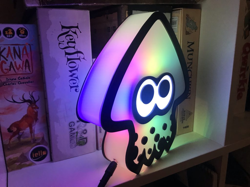
This is part 1 – covering the creative decisions (both planned and spontaneous) made when assembling this Splatoon-inspired lamp.

Concept
I’ve had this idea bouncing in the back of my head for yeeeears – ever since I saw this line in the depths of Ikalog:
# IkaOutput_Hue: "Cameleon" Phillips Hue Lights.Phillips Hue? Huh? Like… the smart lights? Does this code push colour updates to smart lights?
    def light_team_color(self, context):
        ...
        team1 = context['game']['team_color_bgr'][0]
        team2 = context['game']['team_color_bgr'][1]
        c1 = self.rgb2xy(team1[2], team1[1], team1[0])
        c2 = self.rgb2xy(team2[2], team2[1], team2[0])
        self.hue_bridge.lights(1, 'state', xy=c1, bri=255, sat=255)
        self.hue_bridge.lights(2, 'state', xy=c2, bri=255, sat=255)
Oh yes, yes it does.
At the time, I was running Splatoon LAN events and I thought to myself…
What if… I made squid-shaped lights to match the player icons that appear at the top of the screen during gameplay?
What if… I also combined it with the uptime tracking code in Ikalog to dynamically change the status of each light based on whether a player was active or splatted?
Then at a LAN, we could have a light stationed in front of each player to emphasise what was happening to them throughout the game!
Then I did nothing with the idea. Every few months I’d longingly watch DIY RGB panel videos on YouTube before getting stuck on deciding how ambitious to make the build and then moving onto something else.
Motivation
When Splatoon 2 came out it set the idea back a bit. Ikalog didn’t receive any updates beyond the Splatoon 2 testfire. In particular, the code to track player uptime in Splatoon 2 needed some creative problem solving; the icons change size based on the game state, making it harder to get a lock on them to determine their correct state. In September last year I did get a version of the tracking working. (I might write a separate blog post about some of this?)
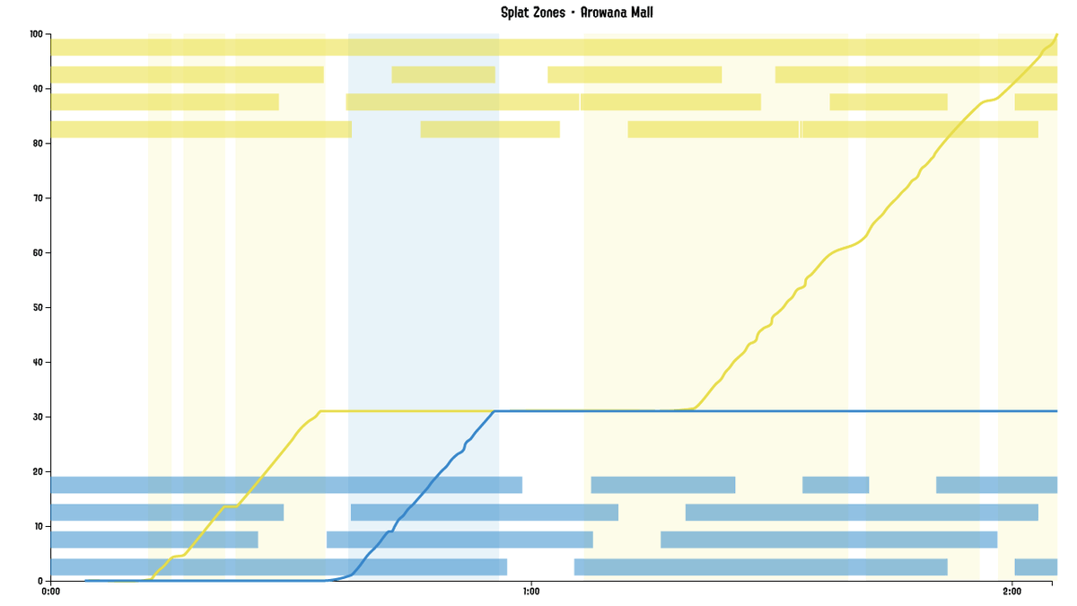
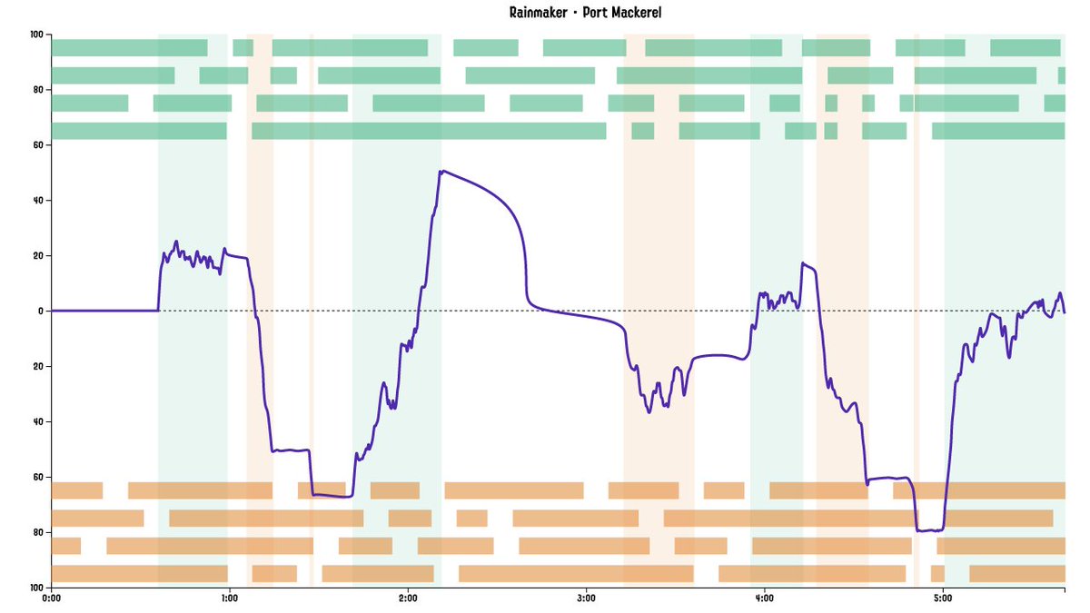
Originally tweeted by @alecatmew on June 30, 2021.
Somewhere in my brain, the Splatoon RGB Light project itched, but it wasn’t strong enough to pull me away from the other projects I was tinkering with at the time. I wasn’t going to be at any LANs for the foreseeable future, so was there any point?
Then, a year later, my dad was working on some lamps of his own – beautiful, intricate wood-carved pieces. I took the opportunity to throw together a nightlight to use with his LEDs.
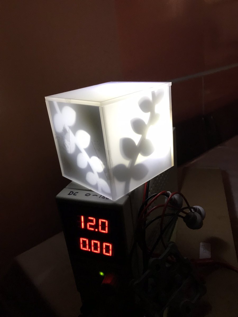
I literally did the designs for the nightlight on the bus, and had it cut and assembled within an hour of getting home.
It was so simple and effective that I got thinking again about the Splatoon light panels. Even if I didn’t get the gameplay integration working, they were going to look cool on their own!
Lamp Design
Before making 8 (or 16, to include Octolings) light panels, I thought I’d start by making a single freestanding lamp, to test the light transmission and generally get a feel for the components involved.
What is a light box made up of? It’s simply a light source with a diffuser. A little distance between the light source and the diffusing material allows the light to have an even glow.
My original mockups for the lamp was a double-shelled container. The RGB light strip would run around the inner perimeter and then pass into another light-blocked area for the eyes, and the space between the two shells would provide room for electronics to be hidden. I ordered a 1m length of WS2812 lights as the light source.
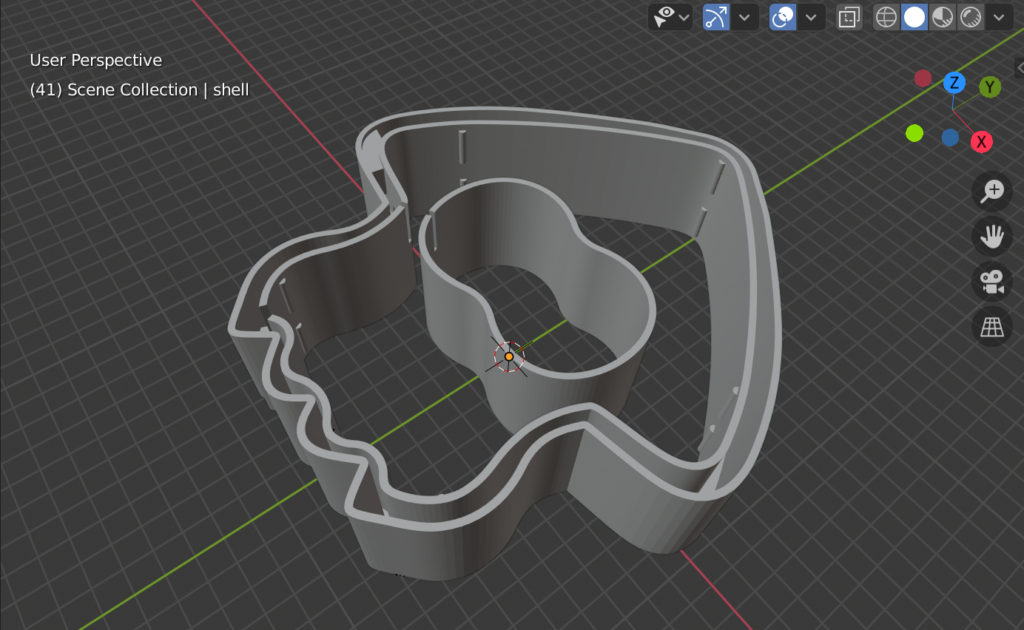
While I have a laser cutter that allows me to cut pieces to accurate size, this design required curved shapes. I contacted 3D Prototypes And Models and Dan quoted >$100 for the printing. The large perimeters being printed up to 5cm tall resulted in an estimated 14 hour print job.
“Ok,” I thought, “I’ll drop the walls to 4cm. I’m willing to pay for one print, maybe I’ll just make the one lamp and end the project there.”
But then I started mocking up how the lamp would look and it felt… too small. I scaled up the design as far as I could to use the full meter of the LED strip. Well now it’s gonna cost even more to 3D print the shell and might be too large for the 3D printers available (not really, but I was starting to look for an excuse to not spend the money on 3D printing when the end goal was to make a number of these things).
Plus, Dan advised that the honeycomb structure of the 3D print would likely show through any illumination from inside the lamp. It was time to tackle things differently…
Acrylic Bending
I have been wanting to experiment with acrylic bending for a while, but the right opportunity hadn’t presented itself. I hadn’t seriously considered it for this project because it seemed too cumbersome to try to accurately bend the pieces. But then I found this video, where the side walls of acrylic lettering was hand-shaped using a heat gun, and I realised this was pretty similar to what I would be trying to achieve.
I asked to borrow my mum’s heat gun, but while waiting for her to dig it up I also had thoughts about making a DIY acrylic bender, or maybe heating up the acrylic in an oven.
Side Story: Toaster Oven
I had a toaster oven that I’d bought second hand to bake polymer clays in (I bought the oven from an older lady named Alethia who did a double take when I responded to her Gumtree post). But after just a few projects the oven had gone unused. So after many years, when I decided I wanted to use it to bend acrylic, I plugged it in and… it tripped the safety breakers in our house.
Tried again, tripped again.
Ok so the toaster oven is bust. Or is it?
I Googled and… there was the suggestion that maybe moisture had built up in the ceramic heating elements, and this was leading to ground leakage. Suggestions to dry them out? Use a hot air gun (still didn’t have mum’s on hand yet) or run it without RCD protection so that it would self-heat and dry.
I looked at the “No RCD” switch under my stove and decided – yeah nah, I better have someone with a little more expertise take a look. After all, did I really want to trust Dr Google with this diagnosis?
So I ended up at the Adelaide Repair Cafe, hosted by Makerspace Adelaide. The lovely folks there helped me to disassemble the toaster oven, to validate that ground leakage was indeed the problem, and to check for any internal corrosion or damage.

One of them did suggest the moisture issue with the elements – based on his own experience of working in physics labs where the equipment would regularly have these issues after going unused for periods of time. So we ran the toaster oven without ground protection and after about 15 minutes it was good to go.
Repair Cafes are great. A fantastic free service to breathe new life into things to save them from landfill – I was so delighted I volunteered to help at their future monthly events.
With that little Sunday afternoon adventure done, it was time to create the full squid assembly!
Structure
By now I’d been able to experiment with the RGB strip and the front and back plates of the lamp.
The plates are made from frosted and black acrylic. The black outline has been modified slightly from the original Squid design to allow for the lamp to rest on the tentacles without tipping to the side.
When cutting the frosted acrylic, I kiss-cut the outlines of where the black would be glued, so that I could find the right positions to place them. By weeding out only the areas where the black will be glued, it also reduces the risk of the frosted acrylic being damaged or marked during gluing and other construction steps.
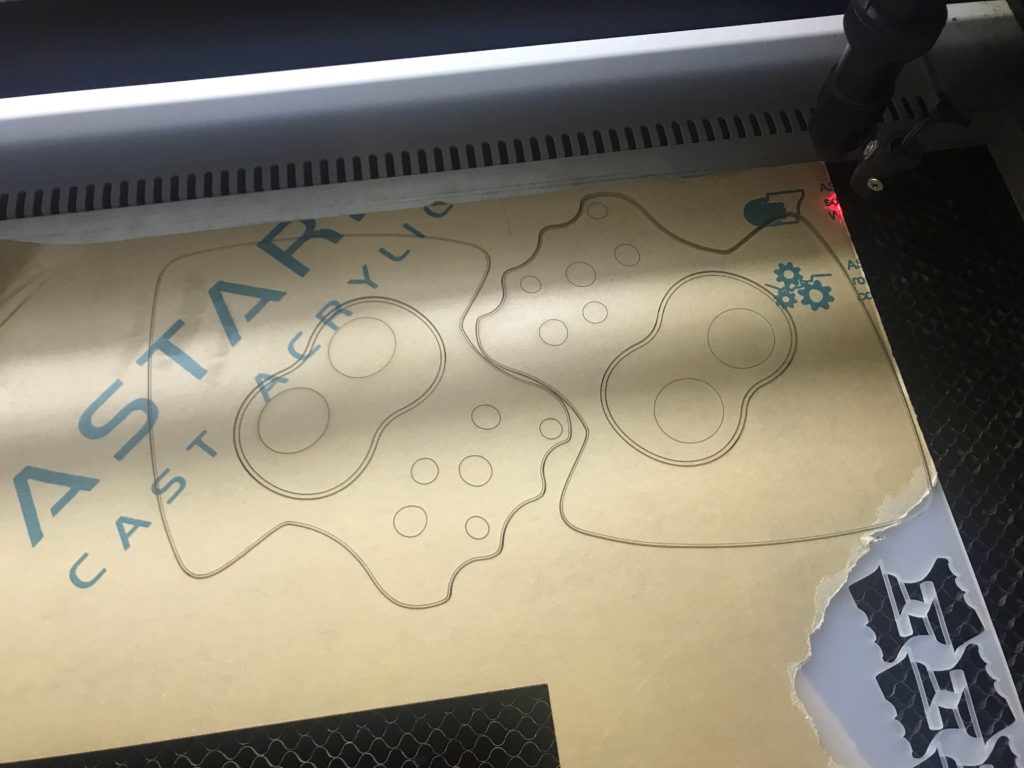
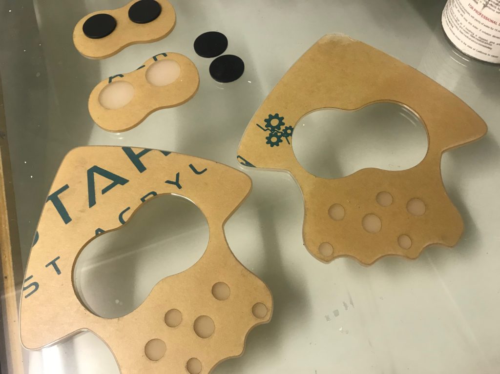
By cutting the eye shape out of the middle of the frosted sheet it leaves a gap that can snugly hold a piece of cardboard. This cardboard serves a few different roles. Firstly, it is the mount point for the white LEDs that will illuminate the eye area. It also blocks the light that white light from blending into the rest of the lamp, and vice versa – keeping the coloured lights from bleeding into the eye area.
Because the cardboard is a tight fit, the two two faceplates can be held together by the cardboard only – and without any of the outer frame being added. Even in the final version of the lamp, I leave one faceplate unglued for easy future opening of the lamp.

This first mock-up of the barrier around the eyes is a bit messy, but for the final version I bent the cardboard along the grain so the curves came out nicer. The edges are also covered in tape to help with fitting into the gap in the frosted acrylic.
After recording the above video, I decided that I could also put the coloured lights on outside surface of the cardboard wall. This meant that I no longer needed the shell to hold the light strip, and with the light being directed outwards… why not allow it to also shine through the outer walls?
So my plan of bending 2mm black acrylic – which would be both easier to bend because of its thickness and (maybe) also because its colour would more easily absorb the heat – became a plan to bend 2mm white acrylic. But that didn’t transmit the light to my satisfaction.
The 3mm frosted (same as the front and back panels) became the goal. I decided to bend the acrylic in 4 segments, to avoid sharp corners. One for the ^ of the squid head, one for each of the sides, and a single curved piece on the base of the lamp, avoiding the pointedness of the individual tentacles.
Forming the Plastic
I made jigs to help form the heated acrylic. My first attempts to bend the acrylic over a jig didn’t work out well because the my gloved hands had trouble guiding the acrylic into the right position. So I added walls to the jig to hold the acrylic. I also added a guide to align the top piece into the bottom piece when pressing the halves together.
For the smaller pieces, I placed the bottom piece in the oven together with the acrylic piece to heat together. Annoyingly, this would affect the fit of my MDF pieces – the MDF would change shape in the heat and the joins would go loose. But other than this, the jigs were pretty effective – provided the acrylic was able to get soft enough. (“Soft enough” seemed to roughly correspond with “when the assembly appears to be smoking” but I need to find a better metric because fire and noxious fumes = bad).
The large piece over the squid head was a pain because it was too large to fit in the oven. I heated it from the ends with the oven door open and slowly it was able to bend enough for me to fit the whole thing in. A light etch in the middle of the piece allowed me to align it correctly with the jig.
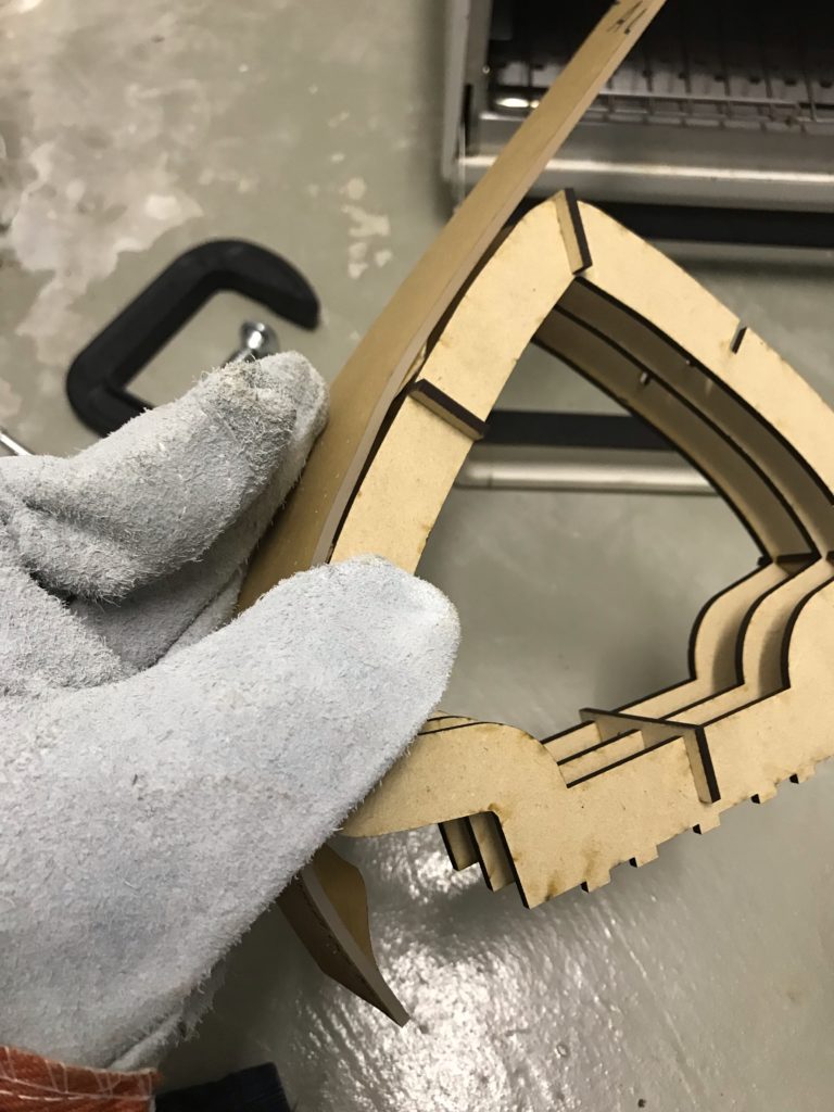
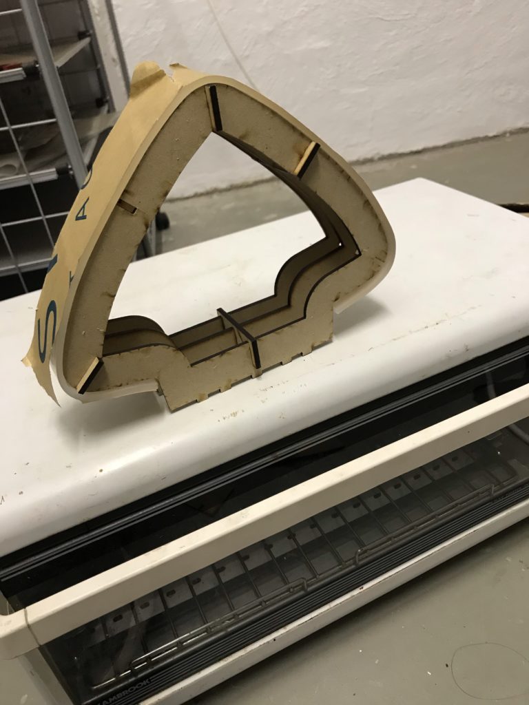
The pieces aren’t bent perfectly, but they’re good enough. I glued them to one of the faceplates and the basic lamp is done!
Circuitry & Software
My LED controller software is wled – run on a Wemos D1 Mini, an ESP8266 board.
wled’s built-in colour palettes and effects are perfect for this use case, and it has a JSON API that I can use push updates from IkaLog if I ever get that integration going.
I chose a 5V LED light strip so that I could run the D1 on the same power source. The lights use 18W per meter and the plan was to use 1m per squid so I sourced a 5V 4A power supply. I didn’t use any logic shifter or resistor in my circuit… probably should, though.
I forgot the data line on the LED strip is directional when I did my first cut-up-and-resolder – which I could have gotten away with without realising if I’d happened to get it right.
The socket fitting was mounted low and centrally, so that the wires coming off it would not be visible through the frosted acrylic. The hole for the socket was cut after the acrylic was bent, and I cut a clear “washer” to affix it to. The end result is a socket that sits nice and flush with the wall!
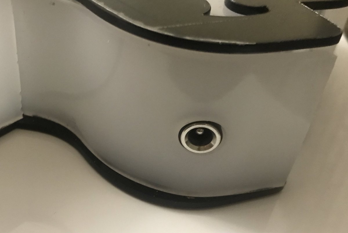
Unfortunately, in the process of doing the final wiring and soldering… this happened.
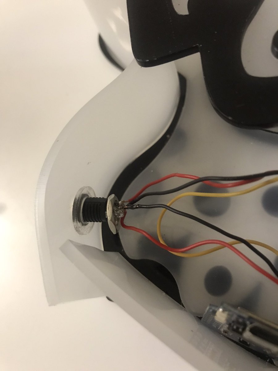
Can you tell what the problem is? When trying to buy a bit more space to move the parts around, I unfastened this nut. Then once everything was reassembled I forgot to screw it back, and with the power plugged in the nut created a short circuit.
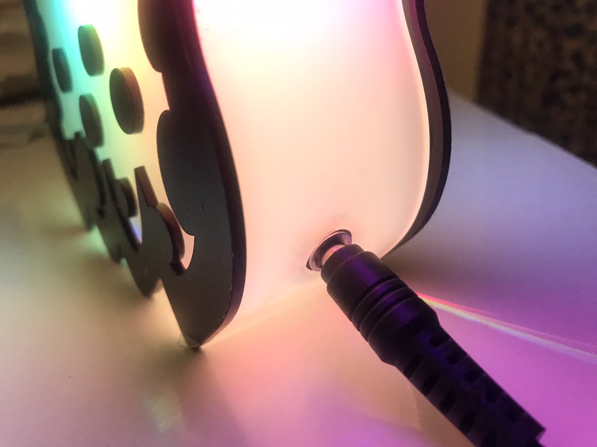
I fried most of my LEDs from this mishap. I salvaged a few unused ones and hey the lamp still looks… ok with partial lighting, but that’s the reason why the photos at the top of this post have a dark patch across one side.
In The Next Episode…
Thoughts for future builds:
Maybe I don’t need that extra loop of LEDs for extra brightness, it actually looks passable with only 12 LEDs (apart from the missing corner). Plus the original idea behind using three loops was so that I could provide data from either end – but that’s moot when the data line is directional.
I need to find a way to make the wire connections without needing to permanently solder things down. Manoeuvring in limited space when everything is stuck together is a pain. Even when we took apart the toaster oven, those connectors had slide on terminals… maybe I need to do the same. So spade connectors, LED strip coupling and header pins on the D1…?
To do the full 4v4 team light panel build, I think I’ll move to a 12V LED strip so that I can chain multiple panels off the same power supply. Using 12V LED strips will require extra components to step down the 12V that will power the LEDs to 5V for the the D1, as well as a logic shifter to convert the 3.3V data line to 5V (I’m getting away without a logic shifter for the 5V LED strip but it sounds like one will be needed for a 12V strip.)
Oh gosh if I do want to get that game integration working I should probably work on that code now before any Splatoon 3 footage appears and affects my motivation again…
